Digital Multimeters
(321)Digital multimeters have become indispensable for technicians handling applications related to electronics, power engineering, electricity, automation, etc. They facilitate the performance of various measurements, thus accelerating diagnostics, installation work, maintenance, etc. They appeared on the market several decades ago and replaced analogue multimeters designed using electromagnetic indicators.
A multimeter is an essential piece of equipment for both professionals and hobbyists. However, each field of application comes with unique, specific needs. When selecting a multimeter, several aspects should be taken into account, i.e.:
- measurement capabilities (values measured);
- operating range (scale, minimum and maximum values);
- sensitivity,
- power supply method,
- and also, in particular in the case of instruments used to handle mains power supplies, product compliance with international and local standards.
See below for an overview of a few key parameters characterising each multimeter and some basic information on selecting a device that is best suited to user’s actual needs.
Basic digital multimeter functionalities
Let us first focus on the basic multimeter functionalities, i.e. functions related to measuring electric values.
AC/DC voltage measurement
Multimeters are primarily associated with three types of measurement, i.e. the measurement of voltage, current and resistance. These are, obviously, the values mentioned in the Ohm’s and Kirchhoff’s laws, which facilitate basic analysis of circuits. Voltage is the first parameter to be checked when diagnosing electronic problems, and it also allows us to estimate the correct connection of power supply components, converters, etc. This functionality can also be used to measure the voltage drop, e.g. across a diode. As it is really likely that a multimeter will be used on both AC and DC circuits, almost every model comes with separate settings for AC and DC. Depending on the main purpose of the device, care should be taken to ensure that its operating range handles measurements on the order of tens of mV DC (for precision electronics) or up to 1 kV AC (mains power installations).
Current strength measurements
Another key value that needs to be measured while handling electronic and electric circuits the current strength, as it facilitates the estimation of the power of a device or component, the energy it consumes, and also makes it possible to compare component performance with nominal parameters, etc. Most multimeters come with two independent ports for current strength measuring. One port is for performing tests in the lower ranges and the other one, protected by a fuse with a higher rating, is used to perform measurements within the maximum scale for which the device is designed (most commonly up to 10 A or 20 A). Before testing such high current strength values, it is essential to ensure that they do not exceed the values specified for probes and leads. A multimeter purchased to measure electronic circuits must handle currents expressed both in mA and µA.
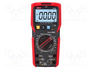
High-end multimeters make it possible to perform True RMS measurements (Root Mean Square). Standard AC current measurement only gives correct results if waveforms are perfectly sinusoidal. In practice, the waveforms often have a different shape (PWM signals, quadratic signals, etc.) or are distorted, e.g. when powering non-linear consumers, semiconductor circuits, switching power supplies, inverters, motors (including air conditioners, domestic appliances, etc.). The True RMS functionality ensures that a multimeter will use sampled data to run calculations whose results will demonstrate the equivalent DC value, i.e. the RMS current value. However, for irregular waveforms, the error range of a “normal” ammeter, i.e. one that measures the average value, can be as high as 40%.
Resistance measurements
The resistance testing feature makes it possible to examine parameters of circuits, wires, connectors or identify SMD components and detect locations of damaged (“burnt”) electronic components. Here, too, the widest possible measuring range should be ensured, most importantly including low values below 1 Ω. It results from the fact that even seemingly small resistance under sufficiently high current results in emitting significant (sometimes hazardous) amounts of heat. This may happen in the case of poorly made connections in switchgear and other network installation points. Performing measurements with an accuracy of a few mΩ makes it possible to detect points of increased resistance. This functionality is also required for precision electronics, where small deviations from nominal parameters can result in detuning of generators, stabilisers, amplifiers, etc. If a multimeter is supposed to handle such circuits, go for equipment offering the four-wire measurement capability, i.e. using the Kelvin method. Traditionally, resistance is tested by measuring the voltage drop across a component through which a current of known strength flows. Unfortunately, the resistance of the leads themselves causes an error to occur, which can be as high as a few dozen per cent when measuring small resistance values (e.g. hundredths of an Ω). In such cases, two independent pairs of leads are used – one ensuring the power supply and the other one responsible for the measurement. This makes it possible to eliminate voltage drops caused by imperfect cabling conductivity and to estimate very precisely the resistance value between the points at which the probes are applied .
Diode and circuit continuity tests
These functionalities are similar, so they are usually adjusted using one setting. The continuity test is one of the basic multimeter functionalities, and it is performed very simply, i.e.: if there is a conductor between the probes that closes the circuit, a multimeter emits a clear, high-pitched sound signal. This signal is meant to alert the user, as continuity tests are often performed over relatively long distances (inspecting mains wiring, vehicle wiring, etc.), so the user is not always near a multimeter when its probe is applied.
The diode test, as the name suggests, is conducted to verify the operation of semiconductor diodes. Such tests are primarily performed for diagnostic purposes, facilitating detection of faulty components. As for diodes that are burned and shorted in both directions (voltage drop close to 0 V, irrespective of polarity), a sound alarm is emitted when the probes are applied, i.e. if a diode with a junction break is detected, an “open circuit” indication is displayed.
Capacitance measurements
This functionality is important primarily when working with electronic components and running circuit diagnostics. The capacity measurement feature enables users to check capacitors for damage or degradation. It is also particularly useful when working with surface-mounted components (SMD), as smaller-format components are not labelled by a printing method, so it is virtually impossible to identify them without running necessary measurements. Note that the results of capacitance tests conducted on a capacitor incorporated in a circuit are always flawed.
Frequency measurements
Sometimes, working with electric and electronic circuits requires checking the frequency of a signal with a regular waveform (e.g. sine wave). In order to test periodic voltage fluctuations with the required precision, an oscilloscope must be used, but relatively often an initial test conducted with a multimeter is sufficient to identify the cause of a fault or verify operation of a generator, inverter etc. A frequency measurement is not a basic multimeter functionality and is available only in selected (usually higher-end) models.
Temperature measurements
The temperature measurement capability is a handy feature offered by numerous multimeters. It is usually run using a thermocouple supplied with the unit. Such tests can be performed within a very wide range (hundreds of °C), depending on the probe used, which enables users to monitor the operation of heaters, boilers, motors, batteries, radiators and a diverse range of other components whose operation relies heavily on correct thermal parameters.
How to choose the right digital multimeter?
It can be assumed that there are three groups of multimeter users:
- specialists involved in the designing, manufacturing and servicing of electronic circuits;
- professional electric engineers working with mains circuits and power lines;
- users requiring basic multimeter functionalities, whether for professional (e.g. car electric system workshops) or private purposes (hobby, minor household repairs).
Note that the parameter range of even very basic multimeters is broad enough to successfully meet the requirements of the third group of users mentioned above. Here, the choice of equipment depends on personal preferences (size, type of display, etc.) and, possibly, its durability. If a multimeter is to be used in harsh environmental conditions (high dust or humidity levels), go for a device offering a high degree of protection of at least IP54, i.e. good dust tightness and resistance to water splashes.
While selecting a multimeter handling electronic circuits, particularly for sensitive semiconductor systems, the best solution is to concentrate on lower measuring ranges which should cover magnitudes in the order of µA, mV, mΩ. As for the other possibilities offered by multimeters: in practice, capacitance, temperature and frequency measurements are not often performed – but when they are needed, an adequate multimeter functionality is extremely valuable.
For electricians, the most important feature of a multimeter should always and primarily be its category as per the standards established by the International Electrotechnical Commission (IEC). This category indicates the type of operations for which a device is intended. It is related to a number of design features of a multimeter: its wiring, connector parameters, material and insulation level. Most commonly, multimeters are classified as follows:
- CAT II (single-phase consumers);
- CAT III (equipment and components of internal three-phase systems);
- CAT IV (single- and three-phase power grid connectors).
On the basis of the part number, each manufacturer must indicate the maximum operating voltage that may be present in circuits tested using a multimeter (usually 300 V, 600 V or 1000 V).
When selecting a device, the would-be user should consider whether a backlit display and keypad could improve their working experience, as many multimeter manufacturers offer such functionalities.
Additional functionalities
For professional applications, additional multimeter functionalities often prove extremely useful. They range from simple convenient features, such as the “hold” function (displaying the measurement when the probes are disconnected) or storing the average, minimum and maximum values, to more complex capabilities. The latter facilitate the inspection of extensive systems, e.g. saving a series of measurements as records. Moreover: high-end multimeters are more and more frequently equipped with Bluetooth and Wi-Fi communication modules allowing the devices to be operated via a phone or tablet, as well as to transmit the collected data over the Internet and storing it in the cloud or on a dedicated server.
Stationary (bench-mounted) multimeters
A popular sub-category of multimeters includes stationary units, i.e. laboratory meters. Their main features include high measurement display resolution (often ten-thousandths of a basic unit), large displays, mains power supply capability and increased sampling frequency. In addition, they offer broader functionalities related to digital measurement analysis. Manufacturers often equip them with additional capabilities, e.g. integrated signal generators. Note that these types of multimeters are designed for professional applications including authorised service workshops or prototyping laboratories, so their prices are relatively high.
Sets
Users looking for a multimeter to upgrade their workshop or putting together a new toolkit should look out for measuring sets offered by numerous brands. They may include, e.g. a multimeter, clamp meter and several add-ons. They are often placed in a dedicated case to help protect the display glass from scratches. In some cases, in addition to the basic equipment (cables, probes), such sets include other accessories, e.g. high-quality crocodile clips, caps, thermocouples, clamp attachments, etc.
Warehouse: