Introduction to Analog-to-Digital Conversion Using a Microcontroller (Part 3)
Introduction to Analog-to-Digital Conversion Using a Microcontroller (Part 3)Date of publication: 18-09-2026 🕒 9 min read
Reliable embedded systems are created when the designer thinks broadly: about hardware, software, work environment, production, and future development. Consistently applying simple, proven principles usually yields better results than complex solutions based on minimal design margins. In the article, we highlight the most important issues that developers should pay attention to and summarize the information presented in a series of three articles dedicated to this topic.
The system as a whole, hardware and software are inseparable connections
An embedded system should be treated as an inseparable connection of hardware and software. Hardware decisions, such as the choice of microcontroller, power supply method, and grounding, always affect the complexity of the code, its reliability, and diagnostic capabilities. At the schematic stage, it is worth considering the programmer's needs related to device startup, testing and measurements, diagnostics, and troubleshooting.
Components with a margin, not "just enough"
The selection of the microcontroller, memory size, computing power, or peripheral modules should take into account the future development of the project. A system that is sufficient today may prove too "weak" to introduce new functionalities or improvements. A resource margin facilitates project maintenance, improves resistance to design errors, and extends the product's life cycle.


Power and ground as key parts of the project
In digital electronics, there's a saying – "if you don't know what's going on, it's about power." Power issues are one of the most common causes of unstable operation in embedded systems. Power should be designed conservatively, using appropriate decoupling capacitors, filtration, and ensuring low impedance of power and ground paths. Separating the analog from the digital part and a well-thought-out PCB layout often has a greater impact on system stability and processing quality than code optimization.
Simplified analog path and signal processing
If the system performs analog measurements, it is worth simplifying the analog-to-digital path as much as possible. Well-chosen voltage ranges, low impedance of the signal source, uncomplicated RC filters, and stable reference voltage usually yield better results than complex algorithms compensating for hardware issues. Software should correct minor errors, not rescue poorly designed electronics.
Software designed for diagnostics and testing
Program code rarely works in ideal laboratory conditions. Therefore, it is worth anticipating diagnostic mechanisms from the start, such as log recording, error counters, critical state signaling, program state (flags) memory at the time of error, or service modes. This significantly shortens the system startup, testing, and later field service time.
Above all, code readability
In embedded systems, simplicity and predictability are often more important than maximum optimization. Code should be readable and understandable, unambiguous, and easy to maintain, even at the cost of a few percent performance. Especially in real-time systems, overly complex program structures hinder error analysis and behavior in boundary situations. From this point of view, if possible, it is worth choosing tools (compilers and programming languages) that ensure proper functionality and solution comprehensibility. For the end customer, the device's functionality matters, for the manufacturer or investor, the time to market, not the language used by the programmer.
Considering working conditions
Temperature, humidity, electromagnetic interference, or vibrations have a real impact on the reliability of embedded systems. The project should consider the target working conditions from the start, both in component selection and PCB and enclosure design. The operation of the final system often looks completely different than on the designer's desk.
Calibration and compensation only where it makes sense
Calibration of the converter, temperature compensation, or sample averaging can significantly improve system performance, but should not be used without reflection on the device itself and solution readability. The best results come from combining a solid hardware design with moderate, well-documented software processing. Calibration should be treated as a tool for improving precision, not as a way to mask design errors.
A good design considers production and service requirements
A good embedded system is not just a working prototype. From an early stage, one should think about production tests, programming microcontroller systems and others, hardware and software version identification, and future update possibilities. Test points, programming connectors, and clear version identification placed in accessible locations can significantly reduce production and maintenance costs.


Documentation, documentation, documentation!
Documentation is not an add-on but part of the project. Describing assumptions, compromises, known limitations, and architectural decisions facilitates system development, onboarding new people into the project, and diagnosing problems. This is especially important after several years when even the most involved people in the project will only vaguely remember the adopted solutions. In embedded systems, knowledge "in the designer's head" often disappears faster than the product itself.
Documenting design decisions applies not only to the device but also – and perhaps even more so – to the software. Comments should be placed in the program in the lines or modules they pertain to. Do not describe the actions performed by the program, e.g., "send number 0x55 via UART," but provide the meaning of the actions, which will allow understanding the reason in a few years, as the action is most often simply visible.
In conclusion
The most valuable source of knowledge about ADCs, including those embedded in microcontrollers, are materials provided by their manufacturers. They contain information directly resulting from actual tests and measurements performed by the manufacturer. Documents from companies like STMicroelectronics, Microchip, NXP, Analog Devices, or Texas Instruments describe in detail: ADC input behavior, source impedance requirements, RC filter implementation, grounding and power supply, temperature and PCB influence.
Particularly valuable are application notes dedicated to optimization, PCB design for devices operating in mixed-signal domains, power distribution, shielding, and grounding. Even if a microcontroller from another manufacturer is used, the available knowledge and physical laws remain the same.
A very good book is "High-Speed Digital Design" by Howard Johnson, which, although not related to ADCs, excellently explains noise, grounding, impedance, and coupling issues, which are also crucial in analog-digital paths. A great complement is "Analog Circuit Design" by Bob Pease, which helps understand the "analog thinking" needed when working with ADCs.
Designing a PCB with an ADC requires more than just knowing the general converter specification. Key information can be found in:
- reference manual (ADC path description, sample & hold, operating modes),
- datasheet (static and dynamic parameters, temperature characteristics),
- errata (real system limitations).
Manufacturers often directly provide the recommended ADC input connection scheme, example RC filters, and capacitor requirements for VREF and VDDA leads. Treating these recommendations as "optional" is one of the most common causes of measurement problems.
For designing embedded system PCBs with ADCs, it is worth using tools that well support working with analog signals and ground planes.
Programs like KiCad, Altium Designer, or OrCAD/Allegro contain tools that: perform ground plane continuity checks, allow defining rules for analog, digital, and power tracks; perform length and proximity analysis of tracks, determine their impedance, allow dividing the board into zones, etc. It is also good practice to use analog simulators, such as LTspice. They allow simulating the ADC input filter, estimating the impact of source impedance and sampling time without soldering prototypes. Even simple RC simulations can reveal design errors at a very early stage.
Designing the analog-digital path does not end with the schematic and PCB. The ability to verify the actual behavior of the system is crucial. In practice, very helpful are:
- an oscilloscope with a good low-capacitance probe,
- a logic analyzer for correlating ADC behavior with digital logic,
- a precise multimeter for measurements and reference voltage checking,
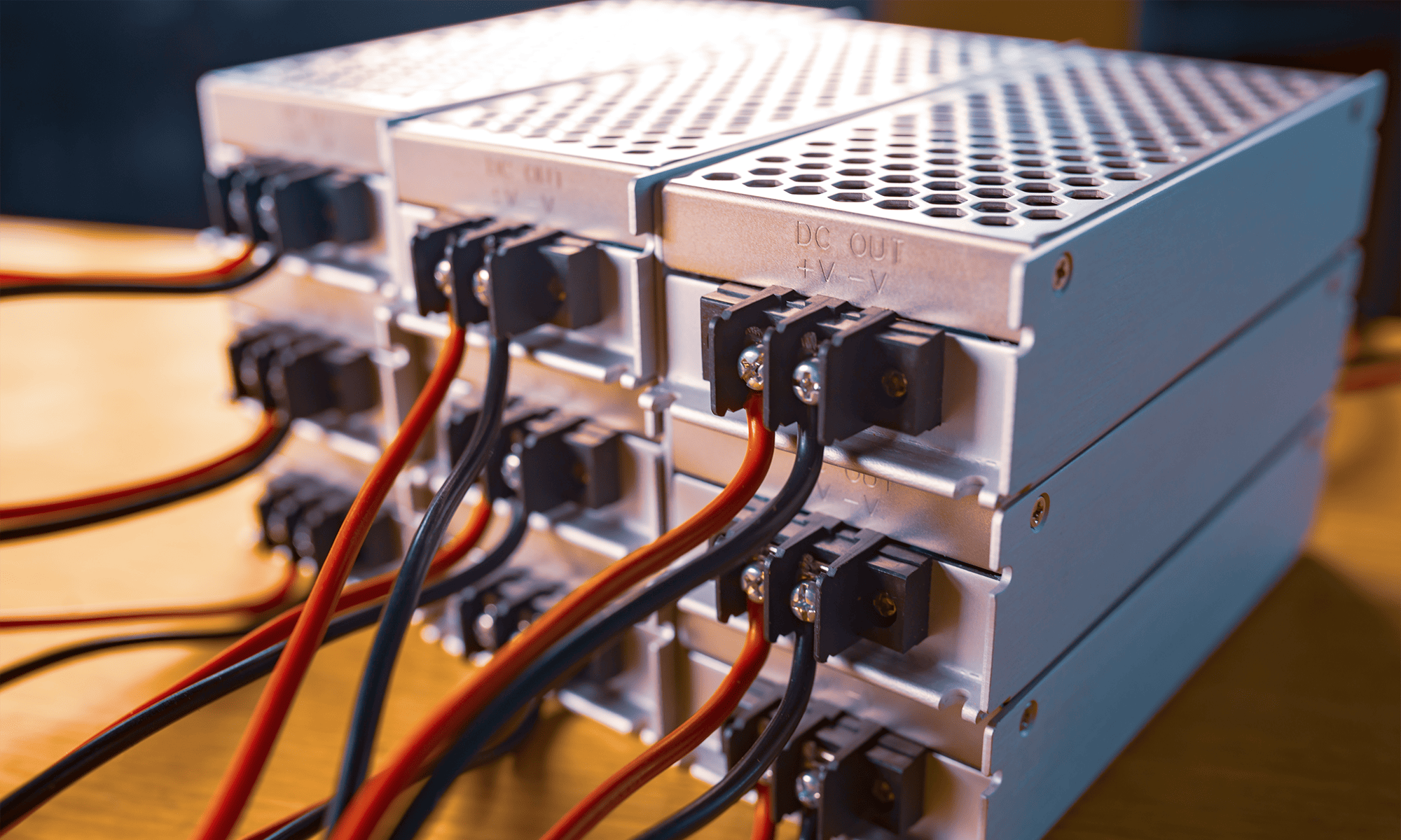
- a laboratory power supply with low noise levels.


The most important tip is to read the documentation and application notes in parallel with your own project. Theory only makes sense when it can be related to a specific schematic and board. It is also worth comparing the recommendations of different manufacturers – recurring schemes and principles are usually the best practices resulting from physics, not marketing.
Transfer Multisort Elektronik (TME) is one of the world’s largest global distributors of electronic components, electrotechnical parts, workshop equipment, and industrial automation. The catalog includes over 1,500,000 products from 1,300 leading manufacturers. TME’s modern logistics centers in Łódź and Rzgów (Poland), with a combined area of over 40,000 m², ship nearly 6,000 packages daily to customers in more than 150 countries.
TME also invests in the development of knowledge and skills of young engineers and electronics enthusiasts through the TME Education project, and supports the tech community by organizing the TechMasterEvent series, promoting innovation and experience exchange.