Breadboard – applications in education and prototyping
Breadboard – applications in education and prototypingDate of publication: 18-08-2023 Update date: 10-04-2026 🕒 8 min read

Breadboard is a device which makes the construction and prototyping of electronic circuits easier. Many people appreciate the breadboard for its versatility, simplicity and the possibility it gives to build practically any electronic circuit really quickly. Also, breadboards help users learn something new about electronics – that’s because the circuitry can be easily modified as you build it, and in this way numerous novel solutions can be tested.
As the name suggests, ”breadboard” has another meaning, and application, too – it’s a board used to slice up bread. The ambiguity may seem strange, but there’s a good explanation for the double meaning. Before universal methods of prototyping were introduced, electronics engineers constructed circuits on boards that were used to slice up bread. They would attach some circuitry components to the breadboard using nails and screws. The wooden layer guaranteed excellent insulation and made it possible to arrange the components freely across its surface. Therefore, a traditional board used to slice up bread can be perceived as the predecessor of our current breadboards used in electronic circuits.
Breadboards in the TME catalogue
How to build prototypes?

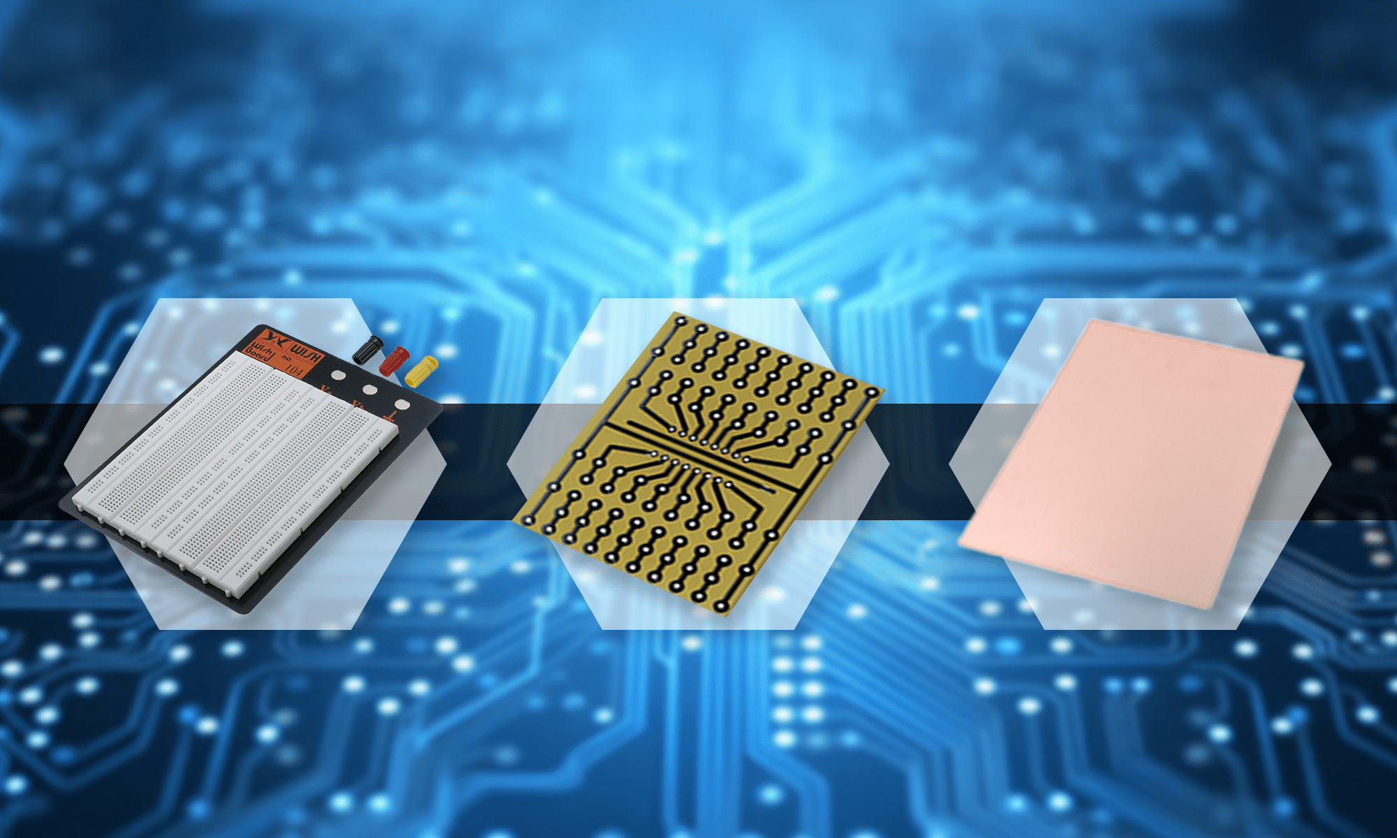
Every electronic circuit consists of a number of components that are connected to each other. In order to check how the circuit works, it has to be designed and built first. There are three ways to construct such a prototype, and each of them has some pros and cons.
- Breadboard – building a prototype on a breadboard is definitely the fastest solution. It’s also easy to modify the circuit if any malfunctions occur. Note, however, that such a circuit is not a permanent solution and, once designed, it should be transferred to a suitable PCB laminate.
- Universal PCB breadboard – building a prototype on universal PCB breadboards is also possible. The components need to be soldered to the board, but if the circuit works, it can be directly incorporated into the target device. Note, however, that it’s much more difficult to modify universal PCB breadboards.
- Dedicated PCB breadboard – one of the options is to devise a dedicated PCB breadboard. Nevertheless, this solution requires a lot of time and some designing skills, so it’s not available to everyone. Besides, if you make a mistake, the breadboard becomes useless, and a new one has to be built. Still, such a circuit is the most professional one.
Breadboard structure and operation

Breadboards are made of plastic, with metal tin plates inside, which, once polarised properly, can conduct current. In the outer layer, there are numerous holes placed at a distance of 0.1 inch (2.54 mm) from each other. That’s one of the most common lead pitch, thanks to which most of the electronic components can be used on the breadboard.
 Connections in the breadboard
If you want to use breadboards, you should first understand how their components are connected to one another. On the top and bottom edges, there are two rails linked to each other horizontally. Their purpose is to conduct the power to other components. Hence, after we supply power, every hole linked in the same line will receive it. The holes placed in the central part of the breadboard are connected in a different way. They create multiple vertical lines, which are divided in half by a small cavity. This means that there are two columns, and they are marked with digit 1 on the board. One of them is above the cavity, and another one below it.
Building a circuit on a breadboard

After understanding the breadboard’s internal structure, it’s time to discuss how to prototype a circuit. It’s a rather simple and quick process, which, undoubtedly, is a crucial advantage of breadboards. The only thing you have to do is place the circuit components on the breadboard, connect the power supply, and the device will be ready for use.

Let’s have a closer look at a simple circuit with an LED, a resistor and a button. The button can be placed above the cavity that is in the central part of the breadboard. In this way, its contacts are available in every hole in column 21 and 23. Now, connect the resistor to the positive powering rail using one pin, and then connect the other one to the column with one button lead. Next, just like in the case of the resistor, connect the LED’s anode to the button, and the cathode to the negative power supply pole. Finally, connect the power supply by plugging the power supply wires into any place on the horizontal rails. Remember, however, not to reverse the poles – on breadboards, the rails are often marked blue for the ground connection and red for the positive power supply pole. It’s worth following the markings, as it may help you avoid problems in the future.
How to choose the breadboard for your needs?
There are many types of breadboards available on the market. They differ from each other mainly in terms of size, which also means that they have various numbers of holes. The most common breadboards have 300 or 820 holes, but there are models with as many as 3000 holes. The choice of the breadboard depends on the desired size of the circuit. Still, it’s worth buying a bit bigger breadboard, as it usually turns out that you could do with a bit more space.

A wide range of breadboards is available
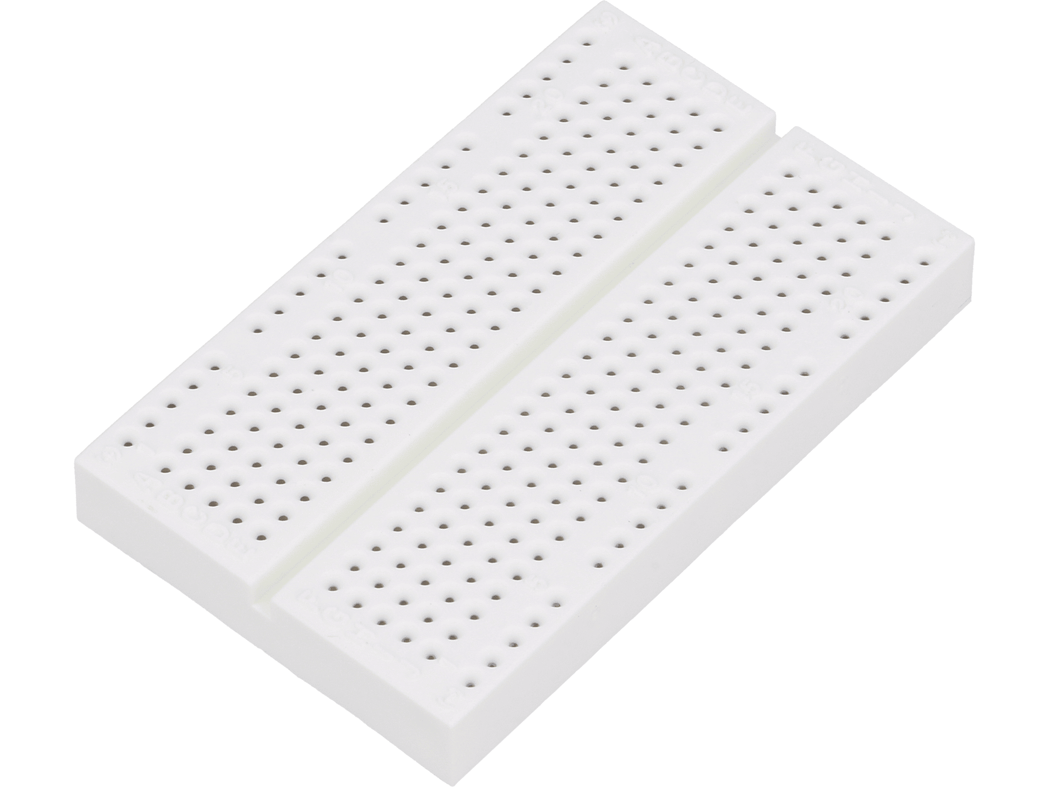
Breadboard with 270 holes
A standard breadboard has two horizontally placed power supply rails, but simpler versions, with only one row of holes, or even without such rails, are available, too.
It's worth noting there’s one more solution to consider – sets of a few breadboards placed on a single base, with additional terminals that make it possible to connect standard wires with banana plugs. It’s quite an interesting product which makes it possible to easily power the circuit using a lab power supply unit.
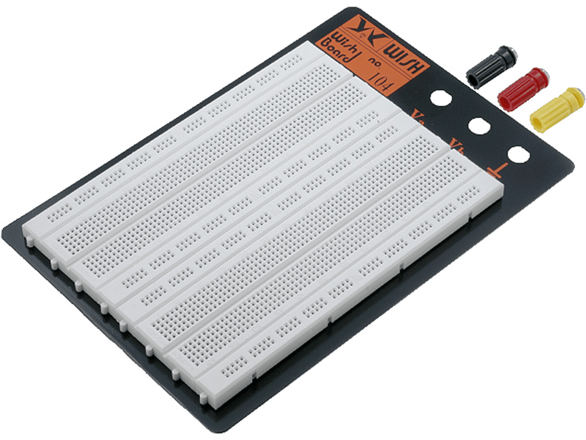
Breadboard with 1280 holes
Accessories for breadboards
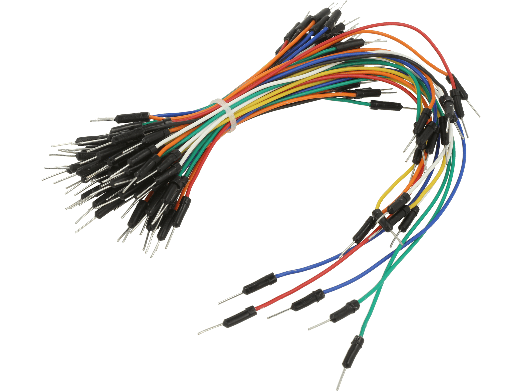
A set of connection wires
Every circuit built on a breadboard must be connected properly. With simple circuits, the components’ leads can be connected directly with other leads, but as the circuit expands, it becomes more difficult to do so. A much better solution is to connect the inputs and outputs with the wires dedicated for breadboards. They differ in terms of length and are terminated with a goldpin connector, which fits perfectly into a breadboard opening.
Jumper links could serve as an alternative for standard connection wires. They are more rigid, so they can be used to build neater circuits in which connections are made directly on the breadboard instead of hanging loosely. Many hobbyists build their own jumper links from Ethernet cables, but it’s not the best solution. Such wires are made of copper, which is fragile, and their terminals aren’t tinned.
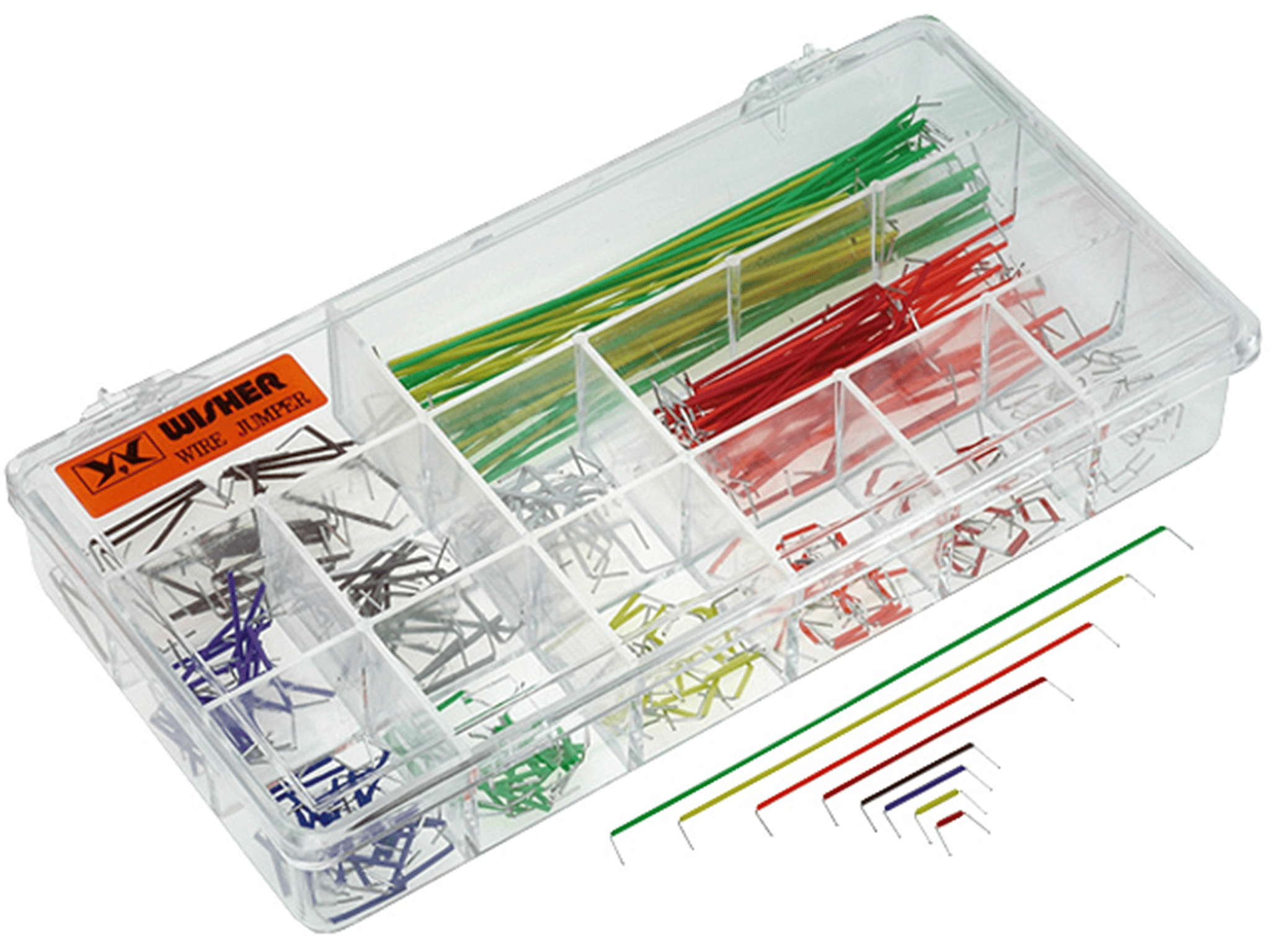
Jumper links in a convenient set
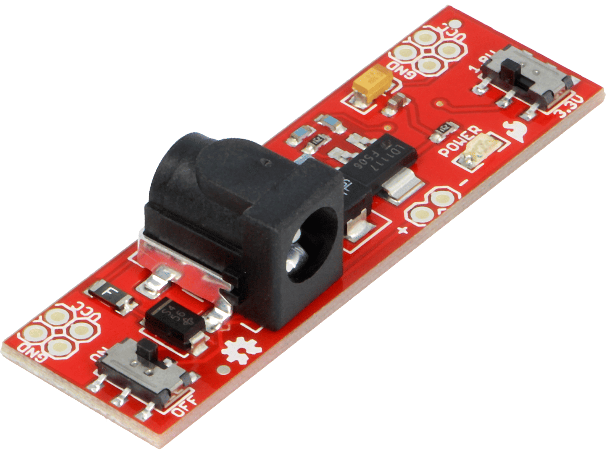
Power supply module which can be plugged to the breadboard
Beside the previously mentioned connection wires, there are many other accessories for breadboards. Above all, these include power supply modules which are plugged directly to the breadboard in order to supply power from a standard PSU using a DC plug. What’s more, quite a lot of adapters dedicated for breadboards are available. They can be used to connect, for example, a USB cable, FFC ribbon cable or even a HDMI connector to a breadboard. In fact, our imagination is the only limitation – if you want to connect something to a breadboard, it’s highly likely that an appropriate adapter already exists. However, if it’s not there, it may be a perfect opportunity to invent one on your own.
Transfer Multisort Elektronik (TME) is one of the world’s largest global distributors of electronic components, electrotechnical parts, workshop equipment, and industrial automation. The catalog includes over 1,500,000 products from 1,300 leading manufacturers. TME’s modern logistics centers in Łódź and Rzgów (Poland), with a combined area of over 40,000 m², ship nearly 6,000 packages daily to customers in more than 150 countries.
TME also invests in the development of knowledge and skills of young engineers and electronics enthusiasts through the TME Education project, and supports the tech community by organizing the TechMasterEvent series, promoting innovation and experience exchange.