Superposition principle in electric circuits
Superposition principle in electric circuitsDate of publication: 05-07-2024 Update date: 10-04-2026 🕒 8 min read

It is generally assumed that electricians’ and electric technicians’ job is quite dangerous. After all, they handle electricity, which means that any mistake can result in tragedy. Their work is seen as difficult and requiring advanced knowledge. However, you do not need to be a master electrician to create an electric circuit, select correct components, or effortlessly determine how current and voltage are to be distributed.
Obviously, we are not talking about complex electric system connections in a smart home here, even though their operation is in principle based on the same laws of physics. There is a source of current that forces electrons to flow in a conductor, at the end of which there is an energy consumer... and this is it. Note here that only an experienced and qualified electrician can build a safe electric system in line with the state of the art, equip it with a well-designed electric switchboard, and conduct relevant measurements. Still, a basic model created for teaching purposes or to pursue a hobby is in fact within everyone’s reach.
- Electric circuits – basic information
- How to apply the superposition principle?
- Is it worth learning the superposition principle?
Introduction to electric circuits
In order to introduce our readers to the arcana of electric circuits, firstly, we must explain what they really are and which components can be integrated in their design. An electric circuit is a system that comprises a conductor and a number of different elements designed to supply electric current to consumers. Its components, such as switches or breakers, facilitate controlling the current flow, alter its course or block it. Electric circuits are described using electric diagrams, in which straight lines indicate the conductor that connects various circuit components, and the other components are represented by device-specific pictographs. The simple diagram presented below will help you understand an electric circuit design and get familiar with its various components.
 Fig. 1 Basic symbols in a linear circuit
The diagram presents key components of each electric circuit. These are:
E1, E2 – voltage sources;
R1, R2, R3 – resistors.
The circuit diagram presented above contains the current source, necessary in each electric circuit to supply a consumer connected with a cable. Obviously, these are not the only components that are present in electric circuit wiring diagrams. Diagrams often include pictographs such as letters A or V in a circle (ammeter and voltmeter, respectively) or an X inside a circle, which symbolises a light bulb. If you are interested in extending your knowledge in this area, make sure to refer to countless free online publications and tutorials providing information on electric diagram symbols.
Why are these diagrams used to describe an electric circuit? They provide the clearest way to represent all circuit components, while showing a complete overview of connections. Thanks to such a standardised set of symbols, regardless of any language barriers that may occur, everyone can understand a system design and make necessary adjustments.
An electric circuit must be closed, as it is only then that the current flow is possible. Additionally, all circuit components must be made of conductive materials.
Electric circuits can be divided into several groups due to certain characteristic features:
1) type of current flowing through a conductor:
- direct current circuits;
- alternating current circuits;
2) consumer connection:
- serial circuits, where the end of the first component is connected to the beginning of the next one. In such systems, a defect in any of the connections results in discontinuing the operation of all other components located upstream;
- parallel circuits, where all electric circuit components have a common beginning and a common end, and are supplied with the same voltage. The difference, however, consists in the fact that each is separated by a separate branch, allowing different currents to flow. A defect in one of them does not affect the operation of the other ones;
- serial-parallel circuits, created by combining serial and parallel circuits;
3) circuit linearity:
- linear circuits, where the Ohm’s law principles are satisfied in all components. In other words, all current sources and consumers have a linear characteristic;
- non-linear circuits, which contain at least one component with non-linear characteristics, and therefore their current-voltage characteristics are not linear.
Now, let us focus on linear circuits and the method of determining current distribution in linear circuits.
Superposition principle – what is it and how to apply it?
The superposition method is one of the methods used to analyse linear circuits. In particular, it is useful for circuits containing two or more independent (current or voltage) sources. Its standard definition is as follows: “A system response to a sum of excitations is equal to the sum of the responses to each excitation separately”. This formula seems to be quite complicated, particularly if you are not quite familiar with the terms used in engineering. Therefore, taking a look at an example in which the calculation of the current flowing in a linear circuit is made can be the best way to understand it.
 Fig. 2 Linear circuit with two current sources
In line with the diagram presented above, this circuit comes with two voltage sources and three resistive components. One of them is located within the main circuit branch. Our task involves drawing the current distribution vectors and calculating their values. Due to the fact that the resistance and voltage values have been selected randomly, calculations are made with certain approximation.
Let us assume the following data:
The first step to determine the current value is to specify its flow directions. It is fairly easy, as the vector of each voltage source shows the direction in which the current flow will be forced. An important issue that cannot be disregarded at this point is the necessity to consider the current in the branch where the resistor is installed.
 Fig. 3 Determining the current flow direction
According to the superposition principle theory mentioned above, in order to consider the whole circuit we can, as it were, divide it into two parts by replacing one of the supply sources with a branch short circuit and, after calculating the current components, proceed with the next one in a similar way.
At this point, note that if we talked about a current source instead of a voltage source, then we would have to replace it with a circuit break. Bearing in mind that the currents flowing through the circuit will be the sum of the two, i.e. one from the circuits supplied by the source, and the other one containing the source, the former is labelled with the “prime” symbol.
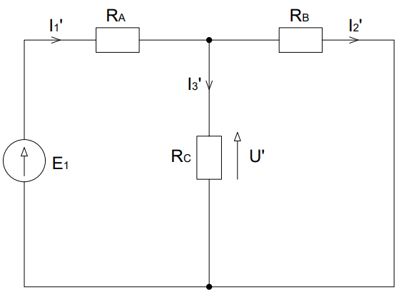 Fig. 4 Replacing one source with a short circuit
As the diagram shown above illustrates, the source has been removed, and, as a result, the sense of the current distribution through the resistor has been changed. At this moment, only one source supplies the whole circuit. With such a circuit form, the equivalent resistance for and must be calculated on the basis of the following relationship:
Next, the current value must be determined:
On the basis of the Ohm’s law, voltage U’ is calculated:
Next, the obtained voltage U’ value facilitates calculating the and current values:
Now, let us concentrate on an analogous circuit, but this time the value will be assumed. Obviously, the current vector directions must be correctly routed also in this case.
 Fig. 5 Replacing the other source with short circuit
Similarly to the case mentioned above, the equivalent resistance for the created electric circuit is calculated:
In this case, the calculated current value is related to another supply source, so it is labelled with the “double prime” symbol:
The voltage is calculated in a similar manner:
Next, the Ohm’s law is used to determine the and current values:
Now, the main circuit current must be calculated. The results obtained are the algebraic sum of the two components. In order to make the calculations correctly, special attention should be paid to the sign preceding the calculated current values. A positive value occurs when the current component vectors are directed in line with the flow in the base circuit, while a negative value occurs when any of the components is opposite to the current in the base circuit.
To sum up, this simple method using the superposition principle enables us to calculate the values of currents flowing through the linear circuit under consideration.
Summary – is it worth applying the superposition method?
The superposition principle is one of the easier methods for calculating current distribution in linear circuits. However, due to the large number of calculations that need to be conducted, in practice it is applied mostly in variants with two or three supply sources. The ability to use this tool to determine the currents in a circuit is one of the foundations of electric engineering expertise and the first step to understand the operating principle of electric circuits. Therefore, it is worth taking the time to become well acquainted with the principle of making calculations using the superposition method, especially at the beginning of your journey into the world of electrical engineering. Obviously, it is not the only method a budding electrician needs to master. With good command of other tools designed to determine the circuit flows (e.g. the Kirchhoff law), you can combine two of them and simplify the calculations.
Transfer Multisort Elektronik (TME) is one of the world’s largest global distributors of electronic components, electrotechnical parts, workshop equipment, and industrial automation. The catalog includes over 1,500,000 products from 1,300 leading manufacturers. TME’s modern logistics centers in Łódź and Rzgów (Poland), with a combined area of over 40,000 m², ship nearly 6,000 packages daily to customers in more than 150 countries.
TME also invests in the development of knowledge and skills of young engineers and electronics enthusiasts through the TME Education project, and supports the tech community by organizing the TechMasterEvent series, promoting innovation and experience exchange.