Electromagnetic interference (EMI): Identification and prevention methods in electronics
Electromagnetic interference (EMI): Identification and prevention methods in electronicsDate of publication: 14-05-2025 Update date: 10-04-2026 🕒 9 min read
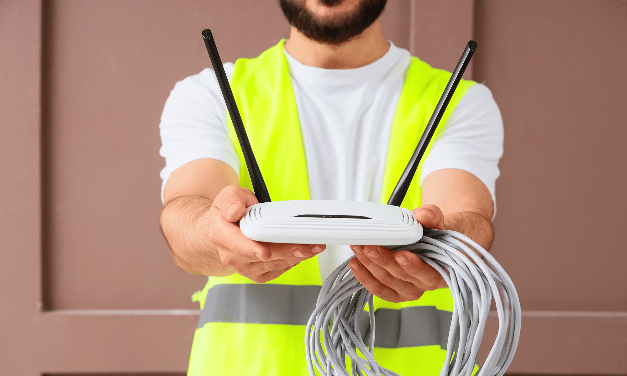
Electromagnetic interference (EMI) are unwanted electrical signals or electromagnetic fields that disrupt the proper functioning of electronic devices. Although this phenomenon has accompanied electronics from the very beginning, its significance is growing with the miniaturization of circuits, the increase in operating frequencies, and the widespread use of wireless communication. A spark in an electric motor, a poorly shielded switching power supply, or a portable Wi-Fi router is enough to disrupt the operation of a neighboring system—from a home Bluetooth speaker to medical equipment or an industrial controller. EMI can result in difficult-to-diagnose failures, transmission errors, device resets, and in critical systems—even threats to health or life. Therefore, identifying sources of interference and effective methods of eliminating them become a key element of every electronics engineer's work.
In the article, we explain what EMI interference is, how to recognize it, how to effectively prevent it, and what standards regulate its permissible level. We will also provide practical examples from various industries—from aviation, through automotive, to home appliances—to show how important proper protection against interference is in today's world full of electronics.
- What is electromagnetic interference
- Identification of EMI interference
- Effects of EMI
- Methods of preventing interference
- Standards and regulations
- Summary
What is electromagnetic interference?
Electromagnetic interference (EMI) is a phenomenon where one electronic device generates an unwanted electromagnetic field that disrupts the operation of another device. In practice, this can be, for example, a computer reset after turning on a motor treadmill or noise in speakers caused by the presence of a mobile phone. EMI occurs wherever current flows—every circuit emits a magnetic field, and variable fields can induce unwanted currents in neighboring circuits. As a result, devices may react unpredictably, freeze, distort data, or lose connectivity.
Electromagnetic interference reaches sensitive circuits in various ways, called coupling mechanisms. In the case of radiation, EMI energy spreads as an electromagnetic wave through the air, similar to radio signals. Conduction means the penetration of interference through common electrical connections, e.g., through the power grid. Capacitive coupling occurs when nearby wires interact with each other through variable electric fields, while inductive coupling occurs when the variable magnetic field of one path induces a current in another.
EMI can be classified according to various criteria. In terms of origin, it is divided into natural interference, such as lightning, solar flares, or cosmic radiation, and artificial, originating from electronic devices, motors, or power networks. In terms of duration, we distinguish between impulse interference, which appears suddenly and briefly, and continuous, lasting for a longer period. Interference can also be narrowband, limited to one frequency, or broadband, covering the entire band—the latter often comes from sparking contacts or converters. The last division concerns the propagation method—conducted interference spreads through cables and conductors, while radiated—through space as electromagnetic waves.
Understanding these mechanisms and classifications is crucial to effectively locating and eliminating EMI sources at the design stage. In the following sections, we will show where interference comes from and how to recognize it in practice.
Identification of EMI interference
Recognizing sources of electromagnetic interference is the first step to effectively protecting devices from their negative impact. With appropriate diagnostic tools and proven methods, engineers can not only detect the presence of interference but also precisely determine their nature and origin.
Diagnostic tools
A wide range of measuring devices is used to detect EMI, allowing for the analysis of both conducted and radiated interference. The basis is spectrum analyzers, enabling the measurement of signal power as a function of frequency—they are indispensable for identifying radio emissions and comparing results with CISPR standards.
Equally useful are electromagnetic field meters, which allow assessing the intensity of interference in a specific working environment of the device. Oscilloscopes enable the observation of interference in the time domain—they detect, for example, sudden pulses or voltage fluctuations associated with the activation of specific components. For local studies, near-field probes are also used, detecting sources of interference at the level of individual PCB components.
More advanced measurements are conducted using LISN (Line Impedance Stabilization Network), which stabilize the impedance during conducted interference measurements and allow their precise detection. For radiated emission studies and immunity tests, specialized anechoic chambers are used, eliminating electromagnetic wave reflections and enabling precise measurements in accordance with international standards.
Products used in EMI diagnostics and mitigation, such as probes, attenuators, filters, or ferrite rings, can be found in TME's offer. Various types of EMC meters and testers are also available, supporting professional diagnostics in laboratories and production lines.
Identification methods
In engineering practice, EMI identification is based on several stages. The first of these are environmental tests, which allow checking how the device behaves in specific working conditions—e.g., near power lines, converters, or communication systems. This helps recreate the conditions in which interference actually occurs.
The next step is locating sources of interference. This can be an element generating internal interference (e.g., DC/DC converter) or an external influence (e.g., a neighboring system or wire). By using near-field probes and an oscilloscope, it is possible to determine the emission site of interference on the PCB or in the device's housing.
In more advanced projects, computer simulations are also used, allowing the prediction of the electromagnetic field distribution in the device even before its physical execution. Analyzing circuit structures and applying enclosure, filter, and shielding models in CAD/EMC software allows for problem elimination already at the design stage.
By combining precise measurements, environmental tests, and simulations, it is possible to effectively identify and neutralize EMI interference—which translates into greater reliability and compliance with standards. If you plan to build or test an electronic system, it is worth reaching for proven EMC components available in TME's offer—they help reduce emissions and increase system immunity already at the assembly stage.
Effects of EMI
Electromagnetic interference can lead to a wide range of technical problems, the symptoms of which are often difficult to diagnose unambiguously. In consumer electronics, the effects of EMI often manifest as temporary performance drops, random device restarts, or image and sound disturbances. A typical example is a computer reset after turning on motorized household appliances connected to the same power network. In digital devices, EMI can cause data transmission errors, operating system instability, or incorrect operation of sensors.
The consequences of interference in critical systems, where reliability directly affects human safety, are decidedly more serious. In hospitals, interference can disrupt the operation of diagnostic devices, such as ECG machines or vital signs monitors. In transportation systems—such as rail vehicles or airplanes—EMI can affect the operation of control systems, automation, or navigation. In extreme cases, errors caused by interference can lead to catastrophic consequences.
Real-life stories show that the EMI problem is not just theoretical. In the 1980s, American UH-60 Black Hawk helicopters experienced unexpected tilts in flight, initially attributed to mechanical failures. Only after a thorough investigation was it shown that strong radio signals penetrated the flight control systems, causing random impulses on the control surfaces. As a result, several crashes occurred, killing dozens of soldiers. The case ended with the redesign of control systems and the addition of shielding to key components.
Another well-documented case is the impact of anti-theft gates in stores on the operation of pacemakers and implantable defibrillators. Patients passing through such systems reported symptoms of heart rhythm disturbances, and in some cases, medical devices triggered incorrect impulses, posing a real threat to life. It also happened that electromagnetic interference caused signal loss in aircraft navigation systems or incorrect sensor readings, especially in the presence of portable devices used by passengers.
These examples clearly show that the effects of EMI can be not only costly but also dangerous. Therefore, when designing and testing electronic devices, it is important to treat electromagnetic compatibility as one of the key elements of the entire system's reliability.
Methods of preventing EMI
Preventing electromagnetic interference is not just about adding filters or shields to a finished device. The most effective approach is to consider electromagnetic compatibility issues already at the design stage. This makes it possible not only to reduce interference emissions but also to increase the device's immunity to external interference.
Design immunity
Even the placement of components on a PCB has a huge impact on interference emissions. Signal paths should be as short as possible, routed close to the ground layer, and avoid creating loops that act as antennas. Where possible, it is worth using full ground layers under circuits, which improves current return and reduces radiation. Avoiding crossings of digital and analog signals and separating power zones from signal zones are also basic design principles.
Shielding and isolation
Physically isolating sensitive circuits is one of the oldest and most effective ways to protect against EMI. Metal enclosures protect the device's interior from interference, acting as a Faraday cage. Using shielded cables, especially in analog transmissions and low-level signals, effectively eliminates coupling from the environment. In critical cases, it is worth considering adding shielded chambers inside the device for the most susceptible circuits.
Filtering
The use of appropriate filters allows for the attenuation of conducted interference already at the source. The most commonly used are LC filters, consisting of inductors and capacitors, which effectively limit the penetration of high-frequency interference through power lines. X and Y class capacitors are designed to work on network lines and help divert interference to ground. Ferrite rings placed on wires add attenuation for higher frequencies and can significantly reduce interference emissions in the simplest way.
Grounding and mass management
The correct architecture of ground connections is the foundation of a resistant electronic system. It is necessary to avoid creating ground loops, which can collect interference from the environment and generate noise. It is best to use a star configuration, where all grounds converge at one point. Cable shields should be grounded on one side, and all metal elements connected to the protective ground in a way that ensures both shielding and user safety.
Distance and separation
Physically separating signal paths from power and routing paths with different purposes in appropriate zones is an effective way to minimize coupling. In installations, it is worth routing power and signal wires separately, preferably in different bundles. Metal or dielectric spacers between modules can limit internal radiation. Where possible, twisted wires should be used, which, due to mutual cancellation of electromagnetic fields, are less susceptible to interference. In the case of transmissions sensitive to interference, fiber optics are a solution almost entirely resistant to EMI.
Software techniques
Protection against the effects of EMI can also be implemented at the software and communication protocol level. Error correction coding, such as CRC or ECC, allows for detecting and correcting errors caused by interference. In industrial and automotive systems, protocols with built-in collision detection and retransmission mechanisms are used. In critical systems, redundancy is often used, where several sensors or control units work in parallel and monitor each other—allowing for the detection of errors caused by EMI and the takeover of functions by backup devices.
The choice of appropriate EMC solutions depends on the device's working environment and its application. To facilitate the implementation of effective protections, it is worth familiarizing yourself with the wide range of products protecting against EMI available at TME. Thanks to them, designing resistant systems becomes much easier and more predictable.
Standards and regulations
Applying effective methods of protection against electromagnetic interference is not enough if the device does not meet formal requirements. In many cases, for a product to be introduced to the market, it must pass compliance tests with applicable EMI and EMC standards. These standards specify not only permissible emission levels but also requirements for device immunity to interference from the environment.
International and regional standards
The basis of the regulatory system is standards developed by international organizations such as CISPR (Special Committee on Radio Interference), operating within the IEC (International Electrotechnical Commission). CISPR standards are widely used in the industry and cover both radiated and conducted emissions, depending on the type of device.
In the European Union, these standards are adopted as EN standards, and in Poland, they are mandatory as PN-EN. An example is the EN 55032 standard, concerning emissions from multimedia devices. Devices introduced to the European market must meet the requirements of the EMC Directive (2014/30/EU), which regulates both emission and immunity to interference.
In the United States, electromagnetic compatibility is overseen by the FCC (Federal Communications Commission), which has introduced its own regulations, including Part 15, specifying emission limits for electronic devices. Despite some differences in measurement methods, many FCC and CISPR standards are mutually convergent, facilitating the introduction of products to international markets.
In terms of immunity to interference, the EN 61000-4-x series of standards is applied, which specifies procedures for testing device immunity to various types of interference—from ESD pulses, through conducted and radiated interference, to voltage dips. Meeting these standards is a condition for obtaining the CE mark and approval for sale in the EU.
Industry requirements
In addition to general standards, there are also specific requirements for individual industries, where device reliability is crucial. In aviation, the DO-160 standard applies, defining procedures for testing avionics for immunity to interference, including strong electromagnetic fields, lightning strikes, or radar interference. Onboard systems must operate flawlessly even in extreme conditions, so the tests are exceptionally rigorous.
In medicine, the basic standard is IEC 60601-1-2, which specifies the permissible emission level of medical devices and their immunity to EMI. This is particularly important because interference can affect the operation of life-support equipment or patient parameter readings. These requirements cover both conducted and radiated emissions, as well as immunity to disturbing pulses.
In the automotive industry, the most commonly used standard is CISPR 25, concerning the limitation of interference emissions from electronic modules in vehicles. Additionally, manufacturers often require compliance with ISO 11452 standards, which describe methods for testing the immunity of electronic systems in the presence of electromagnetic interference in vehicles.
All these regulations have one common goal—to ensure that electronic devices can coexist in an increasingly crowded electromagnetic environment, without interfering with each other and without posing a threat to users. For designers and manufacturers, knowing and applying these standards is not only a formal obligation but also the foundation of the quality and reliability of their products.
Summary
Electromagnetic interference is a challenge that cannot be ignored in any modern electronic project. Practice shows that the key to limiting its impact is the early identification of potential EMI sources and the conscious design of systems with electromagnetic compatibility principles in mind. Short signal paths, a well-thought-out ground layout, the use of shielding and filters are just some of the techniques that can determine whether a device will operate stably in real conditions. Equally important are laboratory tests—both emission and immunity—that allow detecting problems before the product reaches the customer. Implementing EMC principles not only minimizes the risk of complaints but also facilitates certification and market introduction of the device internationally. It is worth treating these issues not as an obligation but as an integral part of engineering quality.
Transfer Multisort Elektronik (TME) is one of the world’s largest global distributors of electronic components, electrotechnical parts, workshop equipment, and industrial automation. The catalog includes over 1,500,000 products from 1,300 leading manufacturers. TME’s modern logistics centers in Łódź and Rzgów (Poland), with a combined area of over 40,000 m², ship nearly 6,000 packages daily to customers in more than 150 countries.
TME also invests in the development of knowledge and skills of young engineers and electronics enthusiasts through the TME Education project, and supports the tech community by organizing the TechMasterEvent series, promoting innovation and experience exchange.