Operational amplifiers and integrated audio amplifiers
Operational amplifiers and integrated audio amplifiersDate of publication: 20-05-2025 Update date: 10-04-2026 🕒 6 min read

Operational amplifiers are small yet highly versatile electronic components found in almost every modern device—from speakers and audio amplifiers to advanced measurement systems. Although their name may sound complex, they are extremely practical circuits that perform one simple function: amplifying electrical signals. In this article, I will try to explain their operation, basic features, and most common applications—particularly in audio equipment.
- Construction and symbol of the amplifier
- Operation of the amplifier
- Key parameters of the amplifier
- Feedback
- Applications of amplifiers
- Perspectives
What is an operational amplifier and what does its symbol look like?
Operational amplifier (often shortened to op-amp) is one of the basic electronic components used in analog circuits. It is an integrated circuit, usually enclosed in a small package, with three main terminals: two inputs and one output.
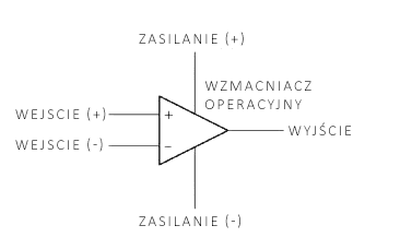
The symbol of an operational amplifier, resembling a triangle, reflects its basic functions. The triangle pointing to the right represents the signal path—from inputs to output. On the left side of the triangle are two inputs:
- Non-inverting input (+) - the signal applied to this input is amplified and retains its polarity (i.e., positive voltage at the input results in positive voltage at the output).
- Inverting input (−) - the signal applied to this input is also amplified but with phase inversion (i.e., positive voltage at the input causes negative voltage at the output).
To the right of the triangle is the output, where the processed signal appears. In real circuits, operational amplifiers also have additional terminals for power supply connection—these allow for providing the appropriate voltage that enables the operational amplifier to function correctly.
How does an operational amplifier work?
The operation of an operational amplifier is based on a very simple principle: it compares the voltages at its two inputs (it can be compared to a precise "voltage scale"). If the difference between the input voltages is zero (the voltages are the same), the signal at the amplifier's output remains stable. However, when the signals differ, the amplifier reacts and amplifies this difference, generating a signal at the output.
A key feature of an operational amplifier is its gain, which in an open loop (without feedback) is very high—typically reaching hundreds of thousands of times.
In real applications, operational amplifiers are usually used with additional components (resistors, capacitors) that allow controlling the gain through so-called feedback. This enables the amplifier to operate stably in various situations—for example, amplifying signals within a specific frequency range or adding signals from multiple sources, thus preventing "overheating," or excessive saturation of the output signal.
Key features of an operational amplifier
Every operational amplifier has a set of parameters that determine its behavior in practical applications.
Open-loop voltage gain
This parameter defines how much the amplifier increases the difference in input voltages when the circuit is not equipped with feedback. An ideal amplifier would have infinite gain, but in reality, this value is about 100,000–1,000,000.
Bandwidth
The bandwidth is the range of frequencies in which the operational amplifier operates best. This parameter defines which signal frequencies can be correctly amplified. In the case of simple operational amplifiers, the bandwidth may be several hundred kHz, while in specialized audio circuits—even several MHz.
Input and output impedance
High input impedance in simple terms means that the amplifier does not load the signal source, which is crucial in precise measurements or audio. Low output impedance allows for easy signal transmission to the next part of the circuit.
Noise
Every operational amplifier introduces some level of interference, known as noise. In audio circuits, amplifiers with minimal noise are used to avoid audible disturbances in the reproduced sound.
Slew rate
This parameter defines how quickly the amplifier can respond, i.e., change the output voltage in response to changing input voltage. A high slew rate is desirable in applications where signals change very quickly, such as in high-quality audio systems.
Feedback – the key to amplifier control
Feedback is the process in which the output signal is partially "returned" to the input of the operational amplifier. There are two types of feedback:
- Negative feedback - involves sending part of the output signal to the inverting input, allowing precise control over how much the amplifier increases the signal.
- Positive feedback - the output signal returns to the non-inverting input, resulting in signal amplification and potentially causing circuit instability. This type of feedback is used in circuits that need to respond quickly, such as flip-flops or signal generators.
Examples of operational amplifier applications
Operational amplifiers are among the most versatile components in analog electronics. Their wide range of functions makes them applicable in countless circuits and applications. Below are several diverse examples that demonstrate the practical possibilities of these integrated circuits.
Inverting amplifier
The inverting amplifier is one of the most commonly used circuits based on an operational amplifier. In this circuit, the input signal is applied to the inverting input (−) through a resistor, and the amplifier's output is connected to the inverting input via a feedback resistor. The non-inverting input (+) is usually connected to ground.
A characteristic feature of this circuit is the phase inversion of the output signal relative to the input. If the input signal is positive, a negative signal appears at the output and vice versa. By using appropriate resistors, the gain can be precisely controlled.
Examples of applications:
- Controlling devices where a change in signal polarity is required.
- Precise measurements in measurement systems where the signal needs to be inverted.
Non-inverting amplifier
The non-inverting amplifier is a circuit in which the input signal is applied to the non-inverting input (+), and the inverting input (−) is connected to the amplifier's output via feedback. In this circuit, the phase of the output signal is consistent with the phase of the input signal, meaning there is no polarity inversion.
Non-inverting amplifiers offer high input impedance, making them ideal for use in circuits where the input signal is very weak and cannot be loaded.
Examples of applications:
- Microphone preamplifiers, where the microphone signal needs amplification without phase change.
- Buffer amplifiers, used in measurement circuits to protect the signal source from loading.
Analog adder
An analog adder, also known as a summing amplifier, is a circuit that allows adding several input signals. These signals are applied to the inverting input through appropriate resistors. The amplifier's output is connected to the inverting input via a feedback resistor.
The analog adder is used wherever it is necessary to combine several signals into one.
Examples of applications:
- Audio mixers, where different sound sources (e.g., microphones, musical instruments) are combined into one output signal.
- Waveform generators that create complex-shaped signals by summing sinusoidal signals.
Schmitt trigger
A Schmitt trigger is a circuit using positive feedback, allowing the conversion of analog signals to digital. This circuit has two switching thresholds—lower and upper—meaning the output changes its state only when the input signal exceeds one of these thresholds.
The Schmitt trigger eliminates the problem of interference near the switching threshold, making it ideal for situations where signals are noisy or unstable.
Examples of applications:
- Shaping digital signals in logic circuits.
- Generating square wave signals, e.g., in digital clocks or timers.
- Voltage detectors that monitor voltage levels in power supply circuits.
Active filters
Active filters are electronic circuits used to pass signals within a specific frequency range and attenuate others. Operational amplifiers are the basis of such filters because they allow precise control of their frequency characteristics.
Types of filters:
- Low-pass filters – pass low-frequency signals, blocking high ones.
- High-pass filters – pass high-frequency signals, blocking low ones.
- Band-pass filters – pass signals within a specific frequency range.
Examples of applications:
- Audio systems, where low-pass filters remove high-frequency noise.
- Radio communication, where band-pass filters separate individual signal channels.
Differential amplifier
A differential amplifier amplifies the difference between two input signals while ignoring any common signals (so-called interfering signals). This makes it ideal for applications where useful signals need to be separated from noise.
Examples of applications:
- Measuring differential voltages in sensors, e.g., in Wheatstone bridges.
- Signal processing in data acquisition systems, where signals must be cleaned of noise.
Voltage regulators
Operational amplifiers are often used in voltage regulators that maintain a constant output voltage level, regardless of changes in supply voltage or load.
Examples of applications:
- Voltage stabilizers in power supply circuits.
- Reference voltage regulators in measurement systems.
Summary and perspectives
Operational amplifiers are extremely versatile and indispensable elements in electronic circuit design, especially in the field of audio and precise measurements. Their versatility results from the ability to control operating parameters through feedback and the wide variety of available models—from standard circuits used in simple applications to specialized circuits with minimal noise or wide frequency ranges.
Despite numerous advantages, operational amplifiers have their limitations, which require consideration in the design process. Thoughtful use of their capabilities allows for the creation of advanced circuits with high functionality and quality.
In the era of audio technology and measurement systems development, operational amplifiers remain one of the most important tools for electronics engineers. Their application, both in classic analog circuits and hybrid digital-analog solutions, will certainly not lose significance for many years.
Transfer Multisort Elektronik (TME) is one of the world’s largest global distributors of electronic components, electrotechnical parts, workshop equipment, and industrial automation. The catalog includes over 1,500,000 products from 1,300 leading manufacturers. TME’s modern logistics centers in Łódź and Rzgów (Poland), with a combined area of over 40,000 m², ship nearly 6,000 packages daily to customers in more than 150 countries.
TME also invests in the development of knowledge and skills of young engineers and electronics enthusiasts through the TME Education project, and supports the tech community by organizing the TechMasterEvent series, promoting innovation and experience exchange.