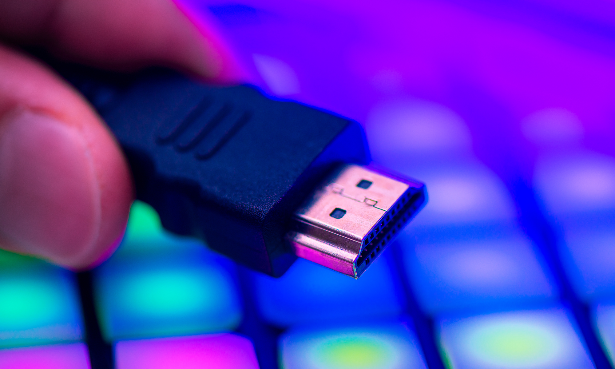
What exactly is USB?
What exactly is USB?Date of publication: 12-12-2024 Update date: 10-04-2026 🕒 16 min read
The history of USB is an interesting tale of the evolution of standards, which perfectly illustrates that reasonable and consistent technological development directly translates into the comfort of life for all of us.
In popular culture, one can encounter the stereotype of a person lost in technological standards and the claim that the various connectors used in consumer electronics or computers create confusion in the life of the average user. Indeed, in the last two decades of the 20th century, the ongoing revolution in the field of IT first created and then deepened the phenomenon known as "digital exclusion", often compared in nature and effects to illiteracy. However, it should also be noted that simultaneously with the advancing computerization, efforts were intensified to create intuitive interfaces and build devices accessible to amateurs. The USB connector, along with the computer mouse or touch screen, is one of the main heroes of this evolution – and everything indicates that it will remain so in the future.
And although the "average Joe" only needs to know that his phone has a USB C port ("And I don't want to know anything more!"), we, electronics enthusiasts, are not satisfied with such simple information. Because we want to know what actually happens when the cable is connected.
In this article, we answer the questions:
- Where did USB connectors come from?
- How does USB work?
- What do the numbers and letters next to the USB abbreviation mean?
- What are the types of USB connectors?
- Does the color of USB matter?
- What is USB C?
- What is USB Power Delivery and can it damage a computer?
- What's new in the USB 4.0 standard?
A brief genesis of the standard
The name USB itself, which stands for Universal Serial Bus, says a lot about the standard. For a precise explanation of this term, another article in the "Electronics from Scratch" series on communication interfaces will be helpful.
Here, let's limit ourselves to basic information:
- Universal - meaning that USB connectors were intended from the start to connect various devices, in the broadest possible range.
- Bus - a physical connection consisting of several lines, adapted to handle a specific type of communication, usually between multiple transmitters/receivers.
- Serial - this word refers to the communication method based on transmitting data in pulses, i.e., bit by bit, using a single line (or two lines in both directions). In the simplest configuration, serial buses need only one transmission wire, making the cabling for such communication affordable and durable, as it can contain relatively large cross-section wires.
The need to develop a universal connector standard became urgent in the 1990s. Computers of that time had serial and parallel ports implemented with sockets of various formats, often with very narrow specialization (separate and different inputs for keyboards and mice, another for the modem, another type for the game controller). They allowed communication with accessories and peripherals but did not automatically detect them, leaving the (not insignificant) burden of configuration on the user.

The USB symbol well reflects the idea behind the standard: connectivity between the main point and peripherals of various kinds (with the open possibility of further communication).
Worst of all, the electrical parameters of the described standards were suboptimal, requiring relatively large amounts of energy to carry out the communication itself, although the current they provided was sufficient to power only the simplest or passive peripherals. The USB standard already inherently solved all of these problems:
- The Plug&Play operation, i.e., "plug and play," anticipated automatic communication between devices at the moment of their connection, and thus: self-configuration carried out by software (by the computer's operating system).
- USB has two lines dedicated solely to power supply. The electrical parameters were sufficient for most peripheral devices from the beginning and were expanded in subsequent generations.
Operating principle
It should be immediately noted here that we will not delve into the full specification of the USB protocol, as the purpose of this text is not to teach hardware interface handling. Nevertheless, let's look at how USB works in general terms. For those interested in details, we recommend the precise and freely available standard documentation.
Cable construction
Although modern USB generations anticipate the use of even a dozen or so lines (more on that later), the minimum number of wires required to establish a connection is 4. They have colors and functions specified by the standard:
- VBUS, the red wire, is the power line with a potential of 5V.
- GND, the black wire, is the ground, i.e., 0V. In the cheapest cables used for charging portable devices, two-wire cables connected only to these two lines are used.
- The green and white wires are respectively D+ and D- or DATA+ and DATA-. These connections are for communication. USB, like many other high-speed interfaces, relies on differential transmission. Binary values are presented simultaneously on two lines, but with opposite polarity (the voltage on one line is the "opposite" of the voltage on the other). This allows for optimal noise immunity even with transmission requiring high signal frequency. USB uses the NRZI method (Non Return to Zero Inverted), where bit 0 is represented by inverting the states on the D- and D+ lines, and bit 1 leaves them at unchanged levels. The communication parties change/check the state on the lines at specified time intervals and thus transmit/receive data.

Male USB A connector and wires contained in a shielded cable.
What happens when USB is connected?
In USB communication, the parties take on the role of host (i.e., the "host" managing the bus) or client (simply called device, or "device"). Of course, right after inserting the plug into the socket, these two circuits know nothing about each other. If the USB device is powered via the bus, as is the case with a flash drive or computer mouse, it is first powered on, so no communication takes place.
Data
Initially, the device informs the host at what speed it intends to communicate during initialization – it does this by setting a high state on the D- or D+ line. From that moment, communication takes place using 8-byte packets transmitted at the indicated frequency.
The first transmission is a packet from the host, which informs the device of its assigned 2-byte address, which will be used in mutual communication. The device responds with an acknowledgment (ACK from the English acknowledgement).
At this stage, theoretically, the USB bus can already be used for communication (e.g., between digital circuits). In practice, the computer (or another circuit acting as the master) will ask the device for its descriptor, a set of data describing the connected equipment. It includes information about the compatible USB generation, device type, manufacturer, and serial number, etc. Most often, based on this information, the operating system can select the appropriate driver, i.e., the program used to handle specific hardware.
Of course, this is just the beginning of the "conversation," the full initialization of the device can be very complex, but this is a specific issue for different types of equipment. In the simplest applications (e.g., projects using the FT232R interface), the integrated circuit connected to USB will present itself as a serial port controller and thus mediate communication between the computer and the microcontroller, transmitting byte strings back and forth, which can be received/sent by a terminal program or other specially written software. And nothing more. In other cases, USB capabilities are used much more broadly: devices can negotiate transmission speed (it is not limited to the two frequencies used during initialization), functionality, protocol, etc.
Power
If the USB cable is connected to the simplest charger, 5V DC voltage will appear on the GND and VBUS lines. The current flowing through the cable will depend on the properties of the given device and the nominal value that the power supply can provide. These parameters are described by a separate standard (Battery Charging Specification), which has undergone several revisions over the past decade due to the increasing demand of mobile devices.
The USB standard also considers the possibility of negotiating voltages and currents present on the power lines. The device descriptor itself already contains data about its electrical specification, including information about the power source and parameters. USB's capabilities in this area were expanded with the introduction of Power Delivery technology, which is described later in the text.
Numbers and letters, explanation of designations
USB is often perceived by users as a complicated technology. This may be due to the numbers, letters, and abbreviations that accompany the name of this interface. But it's not an overwhelming issue if we are aware of the clear division in this nomenclature:
- letters refer to the connector format;
- numbers specify the USB generation (and in practice mainly the transmission speed);
- abbreviations designate additional, optional technologies.
Generations of the standard
Over the past 30 years, the USB standard has been redefined in several generations. Although it may seem like there are many, significant changes did not occur more often than once every 8 years. In the dynamic electronics market, this is an exceptionally cautious pace. Let's look at the most important USB versions:
USB 1.0
The first versions of the standard were not intended for high-speed data transmission, such as transferring large files to portable storage. Accessories connected via USB required relatively low bandwidth, so the speed was limited to 1.5Mb/s and 12Mb/s. These frequencies remain in use at the initialization stage, allowing even relatively old products to remain compatible with the latest computers. Even some new peripherals use this version of the interface because its implementation is cheap, and in many applications, a faster communication method is unnecessary.
USB 2.0
The second generation of USB brought a significant advancement in transmission, accelerating it to 480Mb/s. The power capabilities of the connection also increased, now reaching 1.5A at 5V DC, i.e., power of up to 7.5W. These parameters allowed USB to be used for charging mobile devices, as well as independently powering more demanding peripherals, such as portable hard drives or scanners.
USB 3.0
Versions USB 3.0, and later 3.1 and 3.2, introduced further improvements in data transmission, which now reached up to 20Gb/s (so-called SuperSpeed). Unfortunately, this involved increasing the number of transmission lines and thus redesigning plugs and sockets (more on that shortly). These connectors were designed to remain compatible with previous generations of cables, and only full transmission speed required the use of a special cable. These differences lost significance with the introduction of the USB C format.
Types of USB connectors
And here we come to the issue that causes the most confusion among ordinary consumers – connector formats. The first USB specifications were extremely clear in this regard: there were to be only two types of plugs: A and B. A was used on the host side, i.e., the computer, and the B end was placed in the peripheral device socket. Unfortunately, it quickly became apparent that miniaturization necessitated the development of new, smaller client (B) connector formats. Soon after, laptop and tablet manufacturers, competing to create ever thinner and lighter devices, also saw a problem with the dimensions of the classic, low-profile USB A socket. In response to these demands, the USB C format was created, which can be said to be an even more universal version of the universal interface, using identical plugs and sockets for all types of devices.
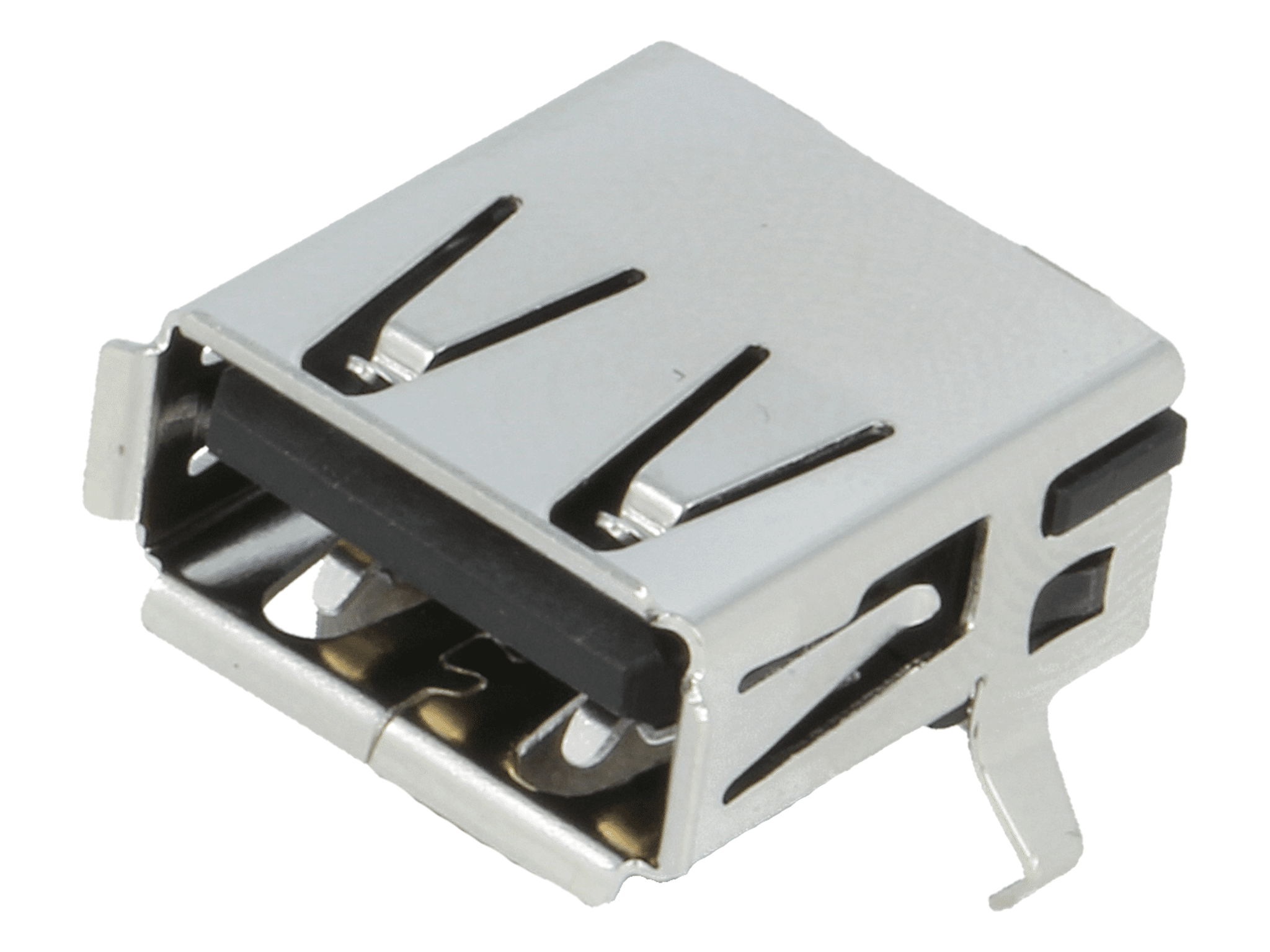
|
USB A | The most basic connector format used primarily in host devices and chargers. Mass-produced in formats for PCB mounting in through-hole (THT) and surface-mount (SMD) technology, as well as connectors for cable mounting. |

|
USB B | Classic client connector format, still found in some peripheral devices, primarily printers and scanners. |

|
USB C | The USB C connector, whose full functionality is described later in the text, is characterized by its small size and symmetrical design, allowing it to be paired in two orientations (180° rotation relative to the plug axis). Sockets of this type are sometimes made in the middle board mount format, intended for installation in a PCB cutout (shown in the photo). This way, a very low connector profile is achieved (less than 1mm above the printed circuit board surface). |

|
USB B mini | USB B mini was the first miniaturized USB format to see widespread implementation in portable devices, primarily larger ones (e.g., cameras). Unfortunately, this variant proved to be still too large for smartphones and other "pocket-sized" devices. |

|
USB B micro | USB B micro is, alongside C, the most popular compact USB socket format. Like the mini version, the connector has one additional pin, which is used to identify devices when connecting two devices intended to work in client mode (see: USB OTG section). |
It should also be mentioned that in the meantime, several other miniaturized USB formats were created, but they did not gain popularity. Ultimately, the functionality and capabilities of USB C made it the de facto standard in global markets and even the official, legally required norm for mobile devices distributed in the European Union markets.

Comparison of plugs of different formats (to scale).
Connector colors
Before we move on to specific versions of the standard, it's worth emphasizing that the color of the connector (or rather its plastic part) also matters. However, it should also be noted that device manufacturers do not always use the color method for identification. Nevertheless:
- connectors in white are compatible with the 1.0/1.1 standard;
- black color is used for devices compatible with at least generation 2.0;
- blue sockets and plugs have additional pins that allow for the full capabilities of the SuperSpeed technology offered with USB 3.0;
- rarely seen turquoise sockets indicate the possibility of transmission at 20Gb/s, which was only possible in the USB 3.2 variant. Sometimes in computers and laptops, you can also find red USB A sockets: this indicates that the port can provide significant currents (usually even after the device is turned off), allowing it to be used for charging smartphones, tablets, etc.

USB connectors on a PC motherboard marked as charging sockets (red) and SuperSpeed (blue).
Special types of connectors for USB SuperSpeed
In several places, we have already encountered SuperSpeed technology. It was introduced in the third generation of the standard. It was a compromise between backward compatibility of USB devices (expected by consumers) and further transmission acceleration. As a result, new plug and socket formats were introduced, where, in addition to the "classic" 4 pins, there were 5 additional connections.
 USB A SS
 USB B SS
 USB B micro SS
The new lines include one additional ground connection (GND drain, no. 8 in the illustration) and two pairs of differential signals (6-7 and 9-10), one for each transmission direction. This means that such connections allow for data transmission in full-duplex mode, i.e., simultaneously in both directions.

The USB micro SS format clearly differs from the original standard, being twice as wide.
Unfortunately, the expansion of connectors, combined with the proliferation of miniature formats, introduced confusion in the USB standard. In short, it became increasingly less user-friendly, especially for people not following technological news. Moreover, compact connectors proved to be vulnerable to accidental attempts to connect the cable in reverse polarity, easily leading to socket damage. Fortunately, all of these problems were eliminated by the new connection format, USB C.
USB C connector pinout
USB C in its full version has 12 connections, but 24 pins. The doubled number results from the mechanical characteristics of the plugs, which can be connected in both orientations, greatly facilitating their use. Importantly: even such an expanded version of the connector for operation in the most basic mode (compatible with USB 1.0 and 2.0) still requires only four lines (even the recommended wire colors have not changed). Of course, in such a minimal arrangement, at least 8 pins should be used to enable symmetrical connection (i.e., "upside down"). In practice, not all USB C lines are always used, and in mobile devices, you can often find simplified versions of the connector (12- and 16-pin), lacking additional lines for accelerated transmission. To understand why further reduction in the number of connections would be problematic, let's look at the construction of the connectors.

All lines of the USB C connector (the illustration shows the socket, i.e., the female version).
The illustration above shows the arrangement and functions of the pins in the USB C socket. Their application is as follows:
| Function | Pin location | Description |
|---|---|---|
| GND | A1, A12, B1, B12 | Ground lines (drain). |
| VBUS | A4, A9, B4, B9 | Power supply, positive potential relative to GND. Standardly, there is still 5V DC voltage here, but the Power Delivery technology described below allows for negotiation of this value. |
| DATA- (D-) | A7, B7 | Basic differential transmission pair, its function is consistent with the indications of generation 2.0 and earlier. |
| DATA+ (D+) | A6, B6 | |
| Tx1-, Tx2- | A3, B3 | From the English transmit. Data transmission pair in the host → device direction, i.e., for example, when writing files to an external drive. |
| Tx1+, Tx2+ | A2, B2 | |
| Rx1-, Rx2- | A10, B10 | From the English receive. Differential signal pair through which data from the device is received by the host (e.g., reading data from an external USB memory). |
| Rx1+, Rx2+ | A11, B11 | |
| SBU1, SBU2 | A8, B8 | Sideband Use is a new, additional line introduced in the C format. It can serve various functions, depending on needs. It is used, among others, in audio device adapters (headphones) and for transitioning from USB to other interfaces (e.g., HDMI). |
| CC1, CC2 | A5, B5 | Configuration Channel (configuration channel). The CC pin is used for role negotiation (host/client) between devices. It is also used in Power Delivery technology. |
Related standards and concepts
With the expansion of the interface, the USB standard began to be accompanied by other related technologies that may (but do not have to) be implemented in devices. We will encounter their names in the documentation of many electronic devices, primarily consumer products such as smartphones or computers.
USB OTG, or On-The-Go
Nowadays, even an ordinary phone (not to mention a tablet) has enough computing power to handle peripherals once reserved exclusively for computers. Examples include printers or pointing devices. The ability to save photos taken with a smartphone on portable USB memory would not be possible if the former did not act as a host. In other words: mobile devices are increasingly managing USB bus communication, and even serve as power sources for accessories. At the same time, they must be able to work as a client (e.g., when connected to a laptop). The USB OTG On-The-Go (from the English phrase meaning "USB on the go") technology anticipates the possibility of negotiating the role of a given device. Currently, this method is implemented at the software level and can be realized using any USB connector – although originally a special type of connector, AB, was anticipated for its implementation, it is now virtually unheard of.
Power Delivery
USB commonly serves as a power connector, becoming the standard for DC connections in consumer devices. However, a laptop or portable speaker requires higher voltages and currents than small accessories (in their case, 1.5A and 5V are sufficient to quickly charge the battery). To allow chargers equipped with a USB connector to work with different types of equipment, the USB Power Delivery specification was introduced in 2012. Currently (2024), its 3rd version (USB-PD 3.1) is in effect. The premise is simple: chargers are equipped with an "intelligent" circuit, i.e., a system implemented using a microcontroller, which negotiates with the connected device the value of voltage and current to be delivered (if the device does not respond, i.e., does not support USB-PD, the values remain at the standard level). The standard defines 8 power profiles, for which the voltage reaches 5V, 9V, 15V, 20V, 28V, 36V, or 48V, and the maximum power ranges from 0.1W to 240W. The CC pin (highlighted above) contained in USB C connectors is used for communication between the power supply and the receiver.
A glance into the future, or USB4
Although we may not realize it, many of us are already using devices compatible with the 4th generation of USB. It was decided to name it USB4 (instead of USB 4.0). It is supported by Windows systems (from version 11), OS X (from Big Sur), and Linux kernels 5.6 and above (Android in devices delivered from 2020). The main change here is, of course, another transmission speed increase, which can now reach up to 80Gb/s (although it should be noted that in practice, few devices can read/write data at such speed). The 4th generation remains backward compatible, but to fully utilize its capabilities, a cable with USB C connectors made according to a specific specification is required. It is worth noting that the dizzying transmission speed currently offered by USB ports is slowly making this technology enter the multimedia realm. Mobile devices, especially tablets, can be connected to an external monitor using just a USB C cable or a USB to HDMI adapter. It is very likely that in the near future, the USB connector will also replace this interface.
Transfer Multisort Elektronik (TME) is one of the world’s largest global distributors of electronic components, electrotechnical parts, workshop equipment, and industrial automation. The catalog includes over 1,500,000 products from 1,300 leading manufacturers. TME’s modern logistics centers in Łódź and Rzgów (Poland), with a combined area of over 40,000 m², ship nearly 6,000 packages daily to customers in more than 150 countries.
TME also invests in the development of knowledge and skills of young engineers and electronics enthusiasts through the TME Education project, and supports the tech community by organizing the TechMasterEvent series, promoting innovation and experience exchange.