Overcurrent switch, overcurrent fuse - how to choose?
Overcurrent switch, overcurrent fuse - how to choose?Date of publication: 14-04-2025 Update date: 10-04-2026 🕒 6 min read
Choosing the right overcurrent protections is important for ensuring the safety of electrical installations. Overcurrent circuit breakers are commonly used in electrical distribution boards, protecting circuits from overloads and short circuits. In this text, we will discuss what overcurrent circuit breakers are, how they work, and what to consider when selecting them.
- What are overcurrent circuit breakers used for?
- How do overcurrent circuit breakers work?
- Installation overcurrent circuit breaker
- How to select an overcurrent circuit breaker
- How to connect an overcurrent circuit breaker
- Selectivity of operation of the overcurrent fuse
- Residual-current device with overcurrent element
What is an overcurrent circuit breaker and what is it used for?
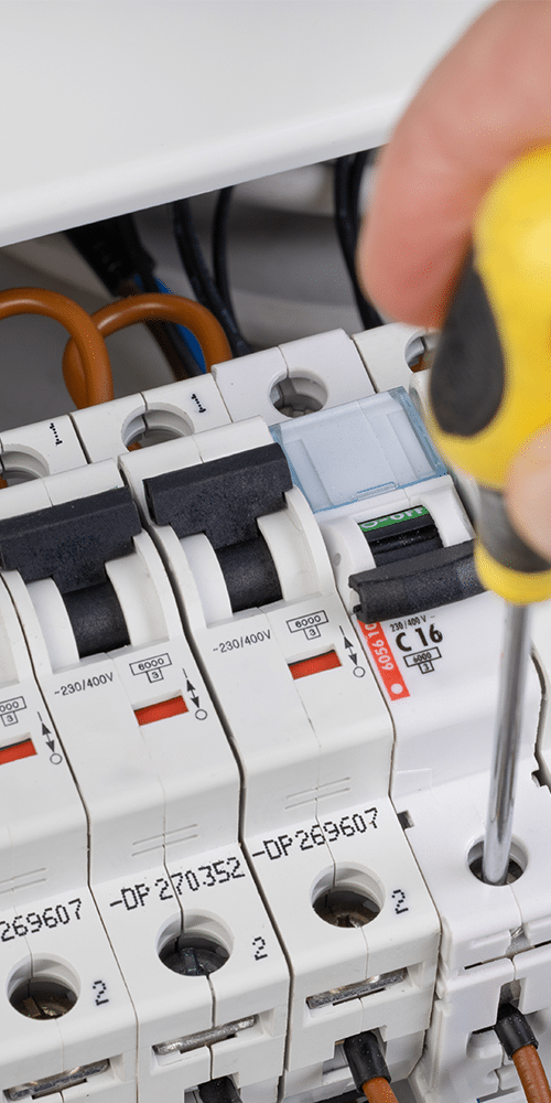
Overcurrent circuit breakers, also known as overcurrent fuses, are electrical devices commonly used in electrical distribution boards. Their task is to protect installations and property from the negative effects of overvoltages, i.e., overloads and short circuits. Before the widespread use of overcurrent circuit breakers of this type, so-called "fuses," i.e., automatic circuit breakers and melting fuses were used.
Short circuits and overloads
An overload is a state in which a current flowing in an electrical circuit exceeds the maximum rated current for a given device or wire. The state of overload results in several adverse effects. First of all, due to the overload, wires and devices start to overheat, and high temperature exposes them to damage. Prolonged overload can cause degradation of wire insulation, which consequently leads to their destruction. Then the risk of short circuits increases. These occur as a result of unprotected insulation wires in the electrical circuit touching each other or due to so-called breakdowns, i.e., temporary or prolonged loss of the electro-insulating properties of the insulation. As a result, a short-circuit current is created, leading to a sudden increase in the intensity of the working current. This can not only damage the electrical installation and receivers but also cause a fire.
Melting fuses and "fuses"
The predecessor of the currently used overcurrent circuit breaker was the aforementioned automatic fuse, and even earlier – the melting fuse. The task of the melting fuse is to cut off the flow of overcurrent to the part of the circuit protected by this fuse. When a current with a significantly higher intensity than the rated flows through the fuse, the melting element (conductor) heats up and then melts in a specific time predetermined by the manufacturer. This creates a break in the circuit, and the melting insert is destroyed, and to restore the flow of current, it must be replaced with a new one, placed in the fuse socket.
In the same socket, "fuses," i.e., automatic circuit breakers, are placed. Their design is relatively simple – the main elements are two triggers: an overload trigger and a short-circuit trigger. The overload trigger reacts to the increased temperature associated with the overload of the circuit by bending the bimetal, while the short-circuit trigger operates on the change of magnetic field. Unlike melting fuses, automatic circuit breakers are reusable – after interrupting the circuit and removing the cause of the operation, they can be switched on again.
Modular overcurrent circuit breakers
Overcurrent circuit breakers serve the same function in an electrical installation as melting fuses and automatic circuit breakers: they protect the circuit from overvoltages. Of course, they differ significantly from their predecessors. They belong to the group of modular electrical devices, with standardized dimensions, designed for mounting on a DIN rail (TH35) in modular distribution boards. A single overcurrent circuit breaker always has a width of 17.5mm (with a tolerance of up to 0.5 mm), a double one 35mm, a triple one 52.5mm, and a quadruple one 70mm. The height and depth depend on the manufacturer, but do not differ significantly. Example dimensions of a single device are 81x17.5x69mm (height x width x depth). Standardization allows for the interchangeable use of circuit breakers from different manufacturers, which facilitates both the design of distribution boards and electrical installations, as well as their later operation.
How do overcurrent circuit breakers work? How to check if they are working?
Each overcurrent circuit breaker has two sections:
- a thermal section, responsible for switching off due to overload,
- an electrodynamic section, responsible for switching off due to a short circuit.
The thermal section is equipped with a bimetallic element and a lever and latch. The flow of overcurrent causes the bimetallic element to bend, which in turn moves the lever. This, after a specified time, opens the latch, interrupting the circuit. In the short-circuit section, on the other hand, there is an electromagnet that opens the circuit immediately after the occurrence of a short-circuit current.
The operating time of the thermal section thus depends on the multiple of the load current, while the operating time of the electrodynamic section essentially does not depend on the intensity. Overcurrent fuses are designed in such a way that they act on short circuits immediately, and on overloads – after a specified time. More on this topic is written in the section on classes of overcurrent circuit breakers.
As for determining the efficiency of operation of overcurrent circuit breakers, it cannot be done in a simple way, as, for example, in the case of residual-current devices, where it is enough to press the "Test" button. To determine whether an overcurrent fuse is efficient or not, it must be subjected to a test using a meter.
Installation overcurrent circuit breaker – technical parameters
In addition to the size, and thus the number of current paths of the circuit breaker, the devices are defined by several other technical parameters, such as time characteristics, voltage, or rated current.
Division of circuit breakers according to voltage and rated current
Overcurrent fuses are manufactured for voltages up to 440V alternating current. The rated currents of circuit breakers, however, cover a wide range: 0.5A, 1A, 2A, 3A, 4A, 6A, 8A, 10A, 16A, 20A, 25A, 32A, 40A, 50A, 63A, 80A, 100A, 125A.
Class of overcurrent circuit breakers
The class of the circuit breaker is directly related to its time-current characteristic, i.e., the relationship between the time elapsed from the moment a disturbance (overload or short circuit) appears and the value of the current intensity of this disturbance. The time-current characteristic determines how quickly the circuit breaker will act at a given intensity of overcurrent. Time-current characteristics of overcurrent circuit breakers are denoted by letters from A to E and further K, L, S, Z. In electrical installations, circuit breakers of class A, B, C, and D are most commonly used. The others occur much less frequently, in specific conditions.
- overcurrent circuit breakers with time-current characteristic A – act immediately and are intended to protect electronic devices sensitive to fluctuations in intensity,
- overcurrent circuit breakers with time-current characteristic B – the most commonly used group of fuses, usually found in residential distribution boards and commercial premises. They are used to protect socket circuits, lighting, and also to protect devices with small starting currents, such as RTV and household appliances,
- overcurrent circuit breakers with time-current characteristic C – ideal for protecting devices with large starting currents (motors, discharge lamps). They are most commonly used in industry,
- overcurrent circuit breakers with time-current characteristic D – used exclusively in industry, protect electro-energy devices with large starting currents (generators, turbines, etc.).
How to properly select an overcurrent circuit breaker?
The parameters of overcurrent circuit breakers are determined by the designer of the electrical installation, and the fuse should always be selected according to the project. However, it is worth knowing how the parameters of the fuse are determined. The device should act before, as a result of the flow of current with a value greater than the strictly defined value for a given wire, the temperature of the wire cores increases above a specified limit value. These requirements are met if:
Ib ≤ In ≤ Iż
I2 ≤ 1.45 Iż
where:
Ib – rated current of the receiver or current adopted for calculations by the designer,
Iz – long-term current loadability of the wire,
In – rated current of the fuse,
I2 – operating current of the fuse.
The operating current of the fuse (I2) is calculated as the product of 1.45 and In for overcurrent circuit breakers with characteristics B, C, and D. In the case of melting fuses or "fuses," the numerical factor is different.
Let's discuss this with a specific example:
We are selecting an overcurrent circuit breaker for a socket circuit in a residential panel. The circuit was made with a single-phase wire laid under plaster YDYp3x2.5mm. The adopted power consumption is 2kW. Since this is a general-purpose residential circuit, we can assume a time-current characteristic B.
From the equation P=UxI, we determine the current adopted for further calculations, i.e., Ib, which in our example is P/U, i.e., 2kW/230V (single-phase circuit), which gives Ib=8.69A.
From special tables, we can read the value of the long-term loadability of the YDYp3x2.5mm wire, i.e., Iz, which is 18.5A.
From the formula Ib ≤ In ≤ Iz, it is clear that the rated current of the fuse (In) must be higher than 8.69A (Ib) and lower than 18.5A (Iz). In our case, both circuit breaker B10A and protection B16A will be suitable. However, since the value of 10A is too close to the value of Ib, i.e., 8.69A, the designer will choose the B16A fuse.
The first condition is met, but it is also necessary to check whether the selected protection meets the second condition, i.e., I2 ≤ 1.45 Iz. For this purpose, the current I2 must be calculated. It turns out that the operating current of the B16A fuse is I2=1.45xIn, i.e., 23.2A. From the condition I2 ≤ 1.45 Iz, it follows that 23.2A ≤ 26.83A.
This means that overcurrent fuse B16A has been selected correctly.
How to connect an overcurrent circuit breaker?
Just like all electrical devices, overcurrent fuses should always be connected according to the manufacturer's instructions. Most often, the phase supply wire is connected to the lower terminal, while the receiver wire – to the upper terminal.
It is worth knowing that in most cases, swapping the wires will not affect the correct operation of the circuit breaker. However, according to the art of installation, if the connection diagram does not indicate otherwise, the supply is connected to the devices from the bottom, while the circuit supplying the receivers – from the top.
Selectivity of operation of the overcurrent fuse
Describing overcurrent circuit breakers, it is impossible not to mention the selectivity of operation of fuses. Selectivity means the necessity of such a selection of protections in the electrical installation that the principle that the protection closer to the place of overvoltage acts faster than the further protection is fulfilled. The further protection serves as a reserve and should act slower than the primary protection. There are two types of selectivity: total and partial. Total selectivity ensures that devices act selectively in every situation, even in unlikely cases. On the other hand, partial selectivity means that devices act selectively only in typical cases of disturbances. In less likely situations, selectivity is not taken into account when designing protections.
Residual-current device with overcurrent element
Electrical installations, devices, property, and also people are protected against the adverse effects of current, i.e., short circuits, overloads, and electric shocks. Overcurrent fuses, protecting against overvoltages, do not serve as protection against electric shock – this function in electrical installations is performed by so-called residual-current devices, i.e., residual-current circuit breakers. However, devices combining protection against overvoltages and electric shocks, i.e., residual-current overcurrent circuit breakers, are increasingly used, especially in home installations.
Transfer Multisort Elektronik (TME) is one of the world’s largest global distributors of electronic components, electrotechnical parts, workshop equipment, and industrial automation. The catalog includes over 1,500,000 products from 1,300 leading manufacturers. TME’s modern logistics centers in Łódź and Rzgów (Poland), with a combined area of over 40,000 m², ship nearly 6,000 packages daily to customers in more than 150 countries.
TME also invests in the development of knowledge and skills of young engineers and electronics enthusiasts through the TME Education project, and supports the tech community by organizing the TechMasterEvent series, promoting innovation and experience exchange.