GPIO functions and applications on the Raspberry Pi
GPIO functions and applications on the Raspberry PiDate of publication: 17-12-2025 🕒 23 min read
It is often heard, that Raspberry Pi single board computers are a very convenient way to start an electronics adventure. But where do the worlds of theoretical programming and printed circuit board actually meet?
TLDR, that is, for the impatient
All ready and already want to start programming? Go here.
Introduction
Raspberry Pi computers were developed as an educational tool. Following the example of British "microcomputers" of the years 80. (inspired by Commodore or Apple products) were by design to offer wide adaptability at a low price. And such a goal was achieved. Raspberry Pi models from the Zero family are even incredibly affordable, while the manufacturer and huge community of engineers/enthusiasts provides untold amounts of teaching materials, aids, libraries, etc. In fact, all you need to develop your skills using Raspberry Pi is enthusiasm. And a little time.
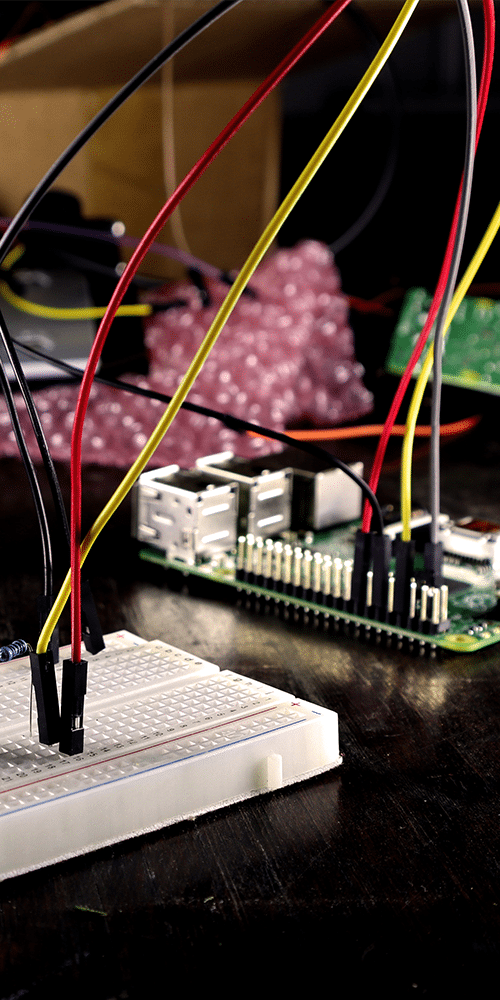
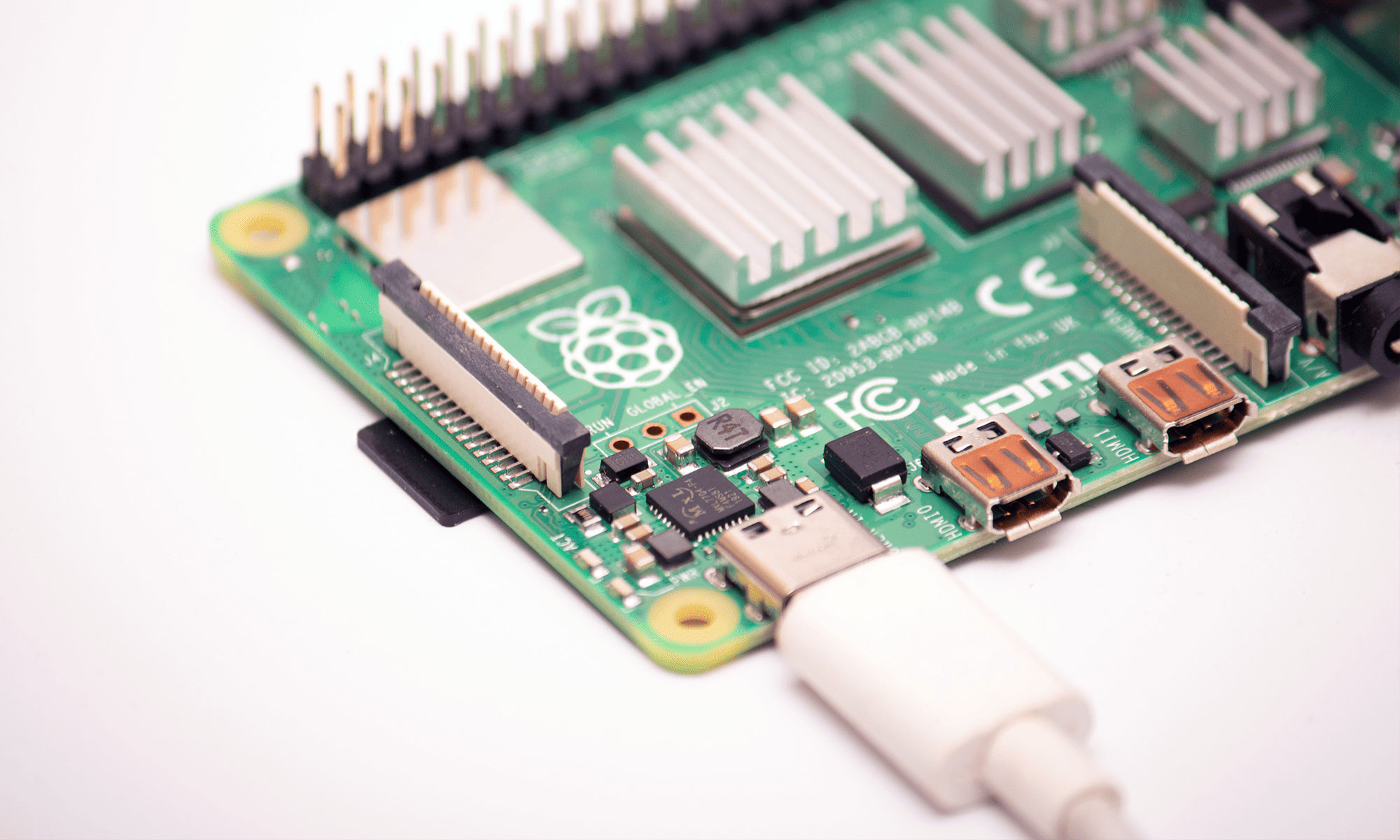
From an electronics point of view, the most important (and certainly the most unique) functionality of the Raspberry Pi is the ability to directly connect the computer to electronic components, electromechanical etc. This is done through GPIO connector - which is not found in laptops or desktop computers. It is the output of the interfaces of the microprocessor and other components of the motherboard, which in other devices are inaccessible to the user. We will look at this connector and its capabilities.
In this article we cover such topics as:
- A discussion of the GPIO and its various functions
- Rasberry Pi's communication interfaces
- How to avoid crashes when learning and developing projects
- The most important development environments for the RPi
- Python libraries to handle GPIO pinouts
- Digital pin input and output support
- Connecting a 230V light bulb to the Raspberry Pi
- Generating square wave signals
- Introduction to the I2C interface
- Products that use the GPIO connector
What is a GPIO?
GPIO stands for General Purpose Input/Output, means general-purpose input/output. And in fact - this is what the specific connection on the RPi motherboard offers. It has undergone only minor changes since the second generation of the computer and is now strictly standardized, so compatible between different versions of the device, always in the same format and offering the same (or at least almost identical) capabilities.
For the format of the connector was chosen very popular "pin" output in the raster 2,54mm (0,1 inch), commonly used in electronics, and above all - education. Compatible pin spacing is based on e.g. contact prototyping boards, leads arduino modules and (literally) millions of components
Layout, types and capabilities of individual pins
Detailed GPIO documentation is widely available on the Internet, so here we will discuss only its basics - and pay special attention to the functions, which can be used virtually immediately after booting up the computer. The following table shows the pin spacing (for reference: pin no. 2 is located nearest the corner of the board):
| power supply | 3,3V DC | 1 | 2 | 5V DC | power supply |
| I2C SDA | GPIO 2 | 3 | 4 | 5V DC | power supply |
| I2C SCL | GPIO 3 | 5 | 6 | GND | power supply |
| GPIO 4 | 7 | 8 | GPIO 14 | TXD | |
| power supply | GND | 9 | 10 | GPIO 15 | RXD |
| GPIO 17 | 11 | 12 | GPIO 18 | ||
| GPIO 27 | 13 | 14 | GND | power supply | |
| GPIO 22 | 15 | 16 | GPIO 23 | ||
| 3,3V DC | 17 | 18 | GPIO 24 | ||
| SPI MOSI | GPIO 10 | 19 | 20 | GND | power supply |
| SPI MISO | GPIO 9 | 21 | 22 | GPIO 25 | |
| SPI CLK | GPIO 11 | 23 | 24 | GPIO 8 | SPI CE0 |
| power supply | GND | 25 | 26 | GPIO 7 | SPI CE1 |
| reserved | - | 27 | 28 | - | reserved |
| GPIO 5 | 29 | 30 | GND | power supply | |
| GPIO 6 | 31 | 32 | GPIO 12 | ||
| GPIO13 | 33 | 34 | GND | power supply | |
| GPIO 19 | 35 | 36 | GPIO 16 | ||
| GPIO 26 | 37 | 38 | GPIO 20 | ||
| power supply | GND | 39 | 40 | GPIO 21 |

The GPIO connector is always in the same position relative to the mounting holes.
Power supply
The power supply pins are divided into those, which provide voltage 3,3V DC (1, 17), 5,0V DC (2, 4), and shorted to system ground (6, 9, 14, 20, 25, 30, 34, 39). The maximum current draw from the GPIO leads is limited and depends on a number of factors. Although theoretically the power supply circuit present on the motherboard can provide 1A for the bus 3,3V, this energy is shared among all components present on the board. In the case of the pins 5,0V - they are short-circuited with the power supply line of the entire computer, so the limitation is the efficiency of the Power Supplies used and the power currently consumed by the computer (this will vary depending on the model of the, software being run, etc.). GND pins share the ground pole with the whole motherboard.
Digital inputs/outputs
All pins labeled GPIO can act as digital inputs and outputs, as well as related functions performed by software (e.g. PWM signal generation, i2C interface emulation). The user can freely set their logical state, which will correspond to voltages 0V for the low state, i 3,3V for the high state. It is also possible to configure these contacts to the role of inputs, that is, checking, whether a voltage has been connected to them 3,3V or 0V has been connected to them - this makes it possible to operate e.g. buttons and switches, by reading their state.
Please note, that under no circumstances should a voltage higher than 3,3V - this will cause permanent damage to the computer.
Similarly: current drawn from the pins, when they act as output, should not exceed several milliamps.
Serial communication interfaces
In practice, the operation of modern electronic circuits is based on communication interfaces, such as the UART, I2C, SPI etc. These are serial communication methods, i.e. involving the transmission of data bit by bit. Such communication can be implemented "hardware-based" (this is handled by a specialized circuit) or "software-based" (the processor directly watches over the transmission and reception of signals by means of digital outputs and inputs). In the first case, the user is forced to use the pins, which the designers have provided to perform a specific function; in the second case, he can freely choose the connection points, but the communication may hinder or delay the operation of the program - but temporarily, at a basic level, such issues we can safely ignore.
I2C
The I2C bus (from a play on words: Inter-Integrated Circuit) is very popular in others electronic devices - but also amateur projects. This is due to its simplicity facilitating software emulation, the possibility of connecting many peripherals, huge tolerance in terms of transmission speed, as well as the wide availability of standard-compliant components and sensors. Only two lines are needed for the interface to work: the clock line (SCL, from signal clock, pin 5) and data (SDA, signal data, pin 3). You can connect (theoretically) 128 independent chips to the bus (including the host chip, that is, in our case, the Raspberry Pi) - each must have a unique address (usually defined to some extent).
SPI
The SPI serial interface ( Serial Peripheral Interface) works slightly differently than I2C, putting a premium on transmission resilience. The GPIO on the Raspbery Pi has two such interfaces, but here we will focus only on the default one (numbered 0).
In SPI communication, instead of addressing individual chips on the bus, each gets its own CE line (Chip Enable), which is used to activate the communication with a given peripheral (pins 24 and 26 allow handling two independent receivers). Other than that, communication is done using two independent lines: one leading from the master circuit (Master) to the slave (Slave), i.e Master Out, Slave In (MOSI , pin 21); and in the reverse direction: Master In, Save Out (MISO), pin 10). The last line is the clock signal, CLK on pin 23.
SPI allows for faster communication than I2C, it can take place in the mode full-duplex (simultaneous data transmission in both directions). The protocol is simple and flexible. Many memories and modules use this transmission method.
UART
In the past, the "serial port" was the basic equipment of every computer, nowadays its function is taken over by the derived standard, USB. UART stands for Universal Asynchronous Receiver-Transmitter, means universal, asynchronous receiver-transmitter. It is a method of communication that has been used for many decades, primarily for sending commands in alphanumeric form. Since in RPi this interface is supported in hardware, buffer handling and data sending is done natively, providing very stable transmission even at higher speeds (typically this will be 9600b/s). The limitation here is , unfortunately, quite restrictive - UART is used for communication between two devices only. Nevertheless, many electronic modules, e.g. GPS receivers, GSM modems (LTE, 4G, 5G) require the use of such an interface.
Two GPIO pins are used for UART communication: transmit (TXD, from transmit, no. 8) and receiving (RXD, receive, no. 10). Remember, that for proper operation, both devices must be set to the same baud rate.
Security and good practices
Before we get into practical applications and examples, let's review security considerations - the two most important ones we've already mentioned:
Voltage only 3,3V DC
Unlike the Arduino, raspberry Pi's logic pins and interfaces (the ones discussed above!) operate on voltages of 3,3V DC. This means, that it will be best to connect circuits operating with such a power supply to the computer - otherwise a level converter (a component that "translates" one voltage range to another).
Save electricity!
Since each GPIO pin can provide 16mA maximum (and the total current consumption should not exceed approx. 50mA), you need to carefully select components so, so as not to overload the capabilities of our computer. To handle higher loads it is best to use intermediate elements (transistors, relay) - about which we will learn more later in the article.
Use Protection diodes and filters
When using components that generate noise and voltage spikes, it is a good habit to use elements suppressing ew. interference (e.g. diodes shorting relay coils, capacitors filtering the voltage at the DC Motors output). This will avoid problems with the program, as well as possible. failure of.
Calmly operate the power supply of the computer and peripherals
We will devote a separate article to the topic of switching Raspberry Pi computers on and off - certainly one thing to note, that under no circumstances disconnecting and connecting the power supply "hot" will not be a good idea. In the case of a computer, it is, obviously, tempting when the program crashes. It is therefore worth remembering, that in Linux (and its terminal) the following is used to abort the program Ctrl+C shortcut. if you want to shut down the computer, it is best to use the command sudo shutdown -h now or sudo poweroff, or. choose an analogous command from the main menu (if using the graphical interface).
As for connecting external components, it is best to do it, when the computer is off. Of course, this is not always practical, e.g. when correcting the work of a program/circuit. In such situations you should simply keep common sense and (even more so) remember to use intermediary components.
Caution is never too much
Finally, let's simply remember to caution. It will allow us to avoid many unnecessary and potentially dangerous mistakes, e.g. short circuits. It is also worth prototype your circuits on a contact board and use different colored cables in standard colors (e.g. black to ground, red to power supply), to more efficiently correct inevitable errors.
Examples of interaction and programming
Since Raspberry Pi systems are based on the Linux kernel, and the whole device is by design to be used for education, we have a wide range of development environments, with which it is possible to interact with the GPIO port. Below we will focus on the Python language, which is fundamental to the British manufacturer's computers, but it is worth knowing the alternatives.
Scratch
For young users just beginning their adventure with programming, an interesting introduction to interacting with electronic components will be Scratch. This visual environment allows you to build complex programs using blocks (each representing an instruction, operator or function) connected on the screen like blocks. Typically, this tools is used to create simple games, etc. Raspberry Pi OS includes a a version of Scratch with additional capabilities: reading and setting logic states on GPIO pins. Adepts can therefore in a few moments realize a a program that operates a switch, LEDs, or even DC Motor Controller.
C/C++
For those familiar with C or C++, communication with the GPIO port will not pose major difficulties. The full version of the RPi system includes the gcc and g++ compilers, so a simple text editor such as nano (also preinstalled) is sufficient to write a program. A library for handling the port will need to be installed. Currently, pigpio is most commonly used for this purpose, or the older (and no longer maintained) WiringPi solution.
Java
The situation is similar with Java, although here you have to install the environment yourself, using the commands sudo apt update and sudo apt install default-jdk. You will then have access to the latest available version of Java. For several years, the Pi4J project (which can be read as "Pi for Java") has been under development, which provides a comprehensive set of development tools to support computer interfaces via Java, via a readable, object-oriented API. The developers here have provided for access to the GPIO pins of the, i2C bus, PWM generator and serial communication.
Node-RED
For those familiar with programming Automation systems, an attractive alternative to the above. options will be the ability to install Node-RED. This is software for executing applications for controlling devices, data processing, etc. It runs in a web browser, so we won't need to connect a monitor to our RPi - it can be placed in a separate enclosure, e.g. electromechanical project, that we are working on. The connection is made via the local IP address of the computer. Node-RED is perfectly suited for creating IoT projects, home automation etc. Installation of the environment is done through a self-published script on the Internet, just type in the terminal bash <(curl -sL https://raw.githubusercontent.com/node-red/linux-installers/master/deb/update-nodejs-and-nodered).
Popular Python modules/libraries
In the case of the Python language, learning is so much easier, because one of the goals of RPi was to popularize this language - which was already held in no small esteem because of its strict philosophy of, transparency and relative simplicity. Users interested in Python's GPIO support have 4 basic libraries to choose from.
RPi.GPIO
First, oldest, is the RPi.GPIO - is not recommended for projects running on the Raspberry Pi computer 5, however, works well with older versions of the device, was also installed by default on Raspberry Pi OS until 2023.
gpiozero
The gpiozero library belongs to the high-level - which means, that it is more user-friendly (it has e.g. ready-made object classes), but may cause delays in program execution. They will be acceptable during learning and in the simplest programs, but in applications that require precision this solution may prove inconvenient. Install the library through the commands: sudo apt update and sudo apt install python3-gpiozero.
pigpio
An alternative supported by all RPi models (from 1A, to 5, including the Zero versions 1, W and 2) is the tools pigpio, which actually consists of two components. A daemon running on the system and a library, which allows you to control it from within Python. This solution has several advantages (speed, compatibility), however, dependence on additional software will not always be desirable. Perhaps the biggest advantage of pigpio is the support of PWM and I2C.
lgpio/libgpiod
The lgpio and libgpiod libraries are based on the so-called "libgpiod". character devices (/dev/gpiochipN). They replace the old approach based on sysfs, which Linux is moving away from. These libraries allow direct, safe and efficient control of GPIO pins. They are recommended for new projects, including Raspberry Pi. Nevertheless: since these solutions are (temporarily) less popular and relatively poorly documented, we will omit them from the following overview.
Setting the state on the GPIO output
To write a program in Python, just open any text editor, place the code in it, and then save it in a file with the format name.py - preferably in an easily accessible place e.g. home folder /home. Then run the script from a terminal, by navigating to the file storage location and using the command python nazwa.py, optionally sudo python nazwa.py (using super user permissions may sometimes be necessary, especially when using the library pigpio).
In the first, simplest example, which is to blink the LEDs connected to the GPIO, we will use the library RPi.GPIO. The electrical connection should look as follows:

Diodes wiring diagram according to the Python script example below.
As for the program code, its content may look like this:
import RPi.GPIO as GPIO
from time import sleep

GPIO.setmode(GPIO.BCM)
GPIO.setup(18, GPIO.OUT)

print("Ctrl+C → STOP")

try:

    while True:
        GPIO.output(18, GPIO.HIGH)
        sleep(1)
        GPIO.output(18, GPIO.LOW)
        sleep(1)

except KeyboardInterrupt:
    print("
Arrivederci!")
    GPIO.cleanup()
After running in the first place, we declare, that it will use the libraryRPI.GPIO library (and refer to it as GPIO), and from the library time we will download only one instruction: sleep (causing the program to pause for a time specified in seconds).
We declare, that in this program we will refer to the pins by their GPIO numbers (according to the table provided in the beginning of the text), and not the order of the pins on the connector: GPIO.setmode(GPIO.BCM). Next, we configure GPIO18 as the output pin.
Next we include an instruction informing the user, that in order to terminate the program, the Control and C key combination must be pressed. In order for the termination to occur correctly and for all actions taken by Python on the GPIO to be aborted, exit must not be "abrupt", that's why we use the construct try … except. It causes, that the code placed in the try block will be executed so long, until a Ctrl+C interrupt is detected (KeyboardInterrupt) - then Python will move to the block except and terminates its operation, greeting the user and releasing the GPIO: GPIO.cleanup().
We write the most important block of the program itself in the form of an infinite loop (similarly, as it happens in the Arduino environment). In other words, instructions located under the while True will be executed over and over again (because the True always meets the condition of being true). In this way, we first set a high state on pin 18 (GPIO.HIGH), then we wait one second, then we set the low state (GPIO.LOW), again wait one second and return to the beginning of the loop. As a result, the connected Diodes will turn on and off, until we interrupt the program.
Controlling a 230V bulb
At this point, let us note, that from the point of view of the program controlling a 230V bulb would look identical. However, the electrical connection would be modified, which would have to be made according to a more complex scheme:
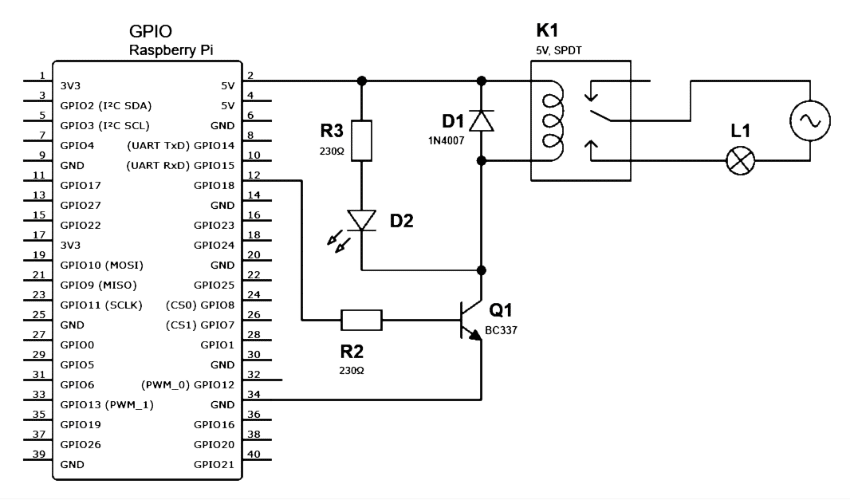
Modification of the schematic for the control of a light bulb powered from a wall outlet.
Closing the circuit of a mains-connected light bulb (L1) is done using a relay (K1) with a 5V DC coil, powered from the GPIO connector. The current flow is made through transistor (Q1), thanks to which a very small base current flowing from the pin is sufficient to control the circuit 18. In the circuit we can additionally place a LED (D2) and its resistor (R2), this will be the transistors trip light. Diodes D1 is a typical protection device, serves to eliminate interference arising at the input of the relay when the contacts return to the rest position, that is, when the circuit is disconnected - in this way the GPIO connector is protected, computer power supply and transistors.
Reading the state of the GPIO
Reading the state on the GPIO pin is just as simple. Let's perform it, this time using the gpiozero library and the two different ways of reading the state on the pin, that it offers.
The schematic for both examples couldn't be simpler:

Just connect the switch between the input pin and GND.
We use a switch with normally open contacts (NO), it can be an ordinary, monostable button, as well as a bistable lever.
The first program code looks as follows:
from gpiozero import Button
from time import sleep

SW = Button(21)

print("Ctrl+C → STOP")

try:

    while True:
        print(SW.value)
        sleep(0.5)

except KeyboardInterrupt:
    print("
Hasta la vista!")
You can see right away, that we are using here a structure similar, as in the first example, so let's focus on the differences. First of all, from the gpiozero library we download only the class Button. Unlike the RPi.GPIO library does most of the configuration for us. All we need to do is create a new object in the Button class and assign pin 21 to it: SW = Button(21). In an infinite loop, we check the state of the switch every half a second and display it in text form: print(SW.value). We will see in the terminal an expanding string of 0 (when the button is released) or 1 (when the switch closes the circuit):
Ctrl+C → STOP
0
0
0
0
0
1
0
1
0
0
1
1
Here it is important to note, that at the time of creating a new object (SW) in the microprocessor, an internal pull-up resistor was connected to pin 21 - and therefore the voltage at the output has a value of approx. 3,3V. When the pin is shorted to GND by pressing the button, the voltage drops below the threshold for logical zero (close to 0V). Nevertheless: the gpiozero library tries to make our lives easier and inverts these binary values. A button pressed is the value 1, while released is 0. This is a good example of simplifications, which for an experienced electronics technician may prove confusing.
A useful feature of the gpiozero library is the ability to to handle interrupts triggered by a change of switch state. An example is presented below:
from gpiozero import Button
from time import sleep

SW = Button(21)

def on_press():
print("ON")
sleep(0.1)

def on_release():
print("OFF")
sleep(0.1)

SW.when_pressed = on_press
SW.when_released = on_release

print("Ctrl+C → STOP")

try:
    while True:
        print(".")
        sleep(0.5)

except KeyboardInterrupt:
    print("
Até logo!")
As you can see, we have two functions here: one displays ON, the other OFF. In both we include a delay of 100ms, so that the program ignores contact tremor, which would cause the same press repeatedly to be reported (so-called. debounce). Then we declare, that at the moment of pressing the button the function is to be executed on_press, and at the moment of releasing it on_release. Then we start our traditional, infinite loop, which in this case symbolizes the execution of Very Important Operations, a de facto serves only to write out a sequence of dots on the terminal at half-second intervals. The column of dots will be interrupted (just like the, as the run of the program), when the state on pin 21 changes. We will then see:
Ctrl+C → STOP
.
.
.
ON
.
.
OFF
.
.
PWM signal generation
To generate the PWM signal we will use the third of the libraries mentioned above pigpio. Importantly: it does not work on its own. After installing the package (sudo apt install pigpio), we still need to run the process running in the background (daemon), which will use the library to handle low-level GPIO interfaces. We enable it, by typing in the terminal sudo pigpiod.
Now we can already test the program in Python:
import pigpio
import time

GPIO = pigpio.pi()
LED = 18

print("Ctrl+C → STOP")

try:

    while True:

        for duty in range(0, 256, 5):
            GPIO.set_PWM_dutycycle(LED, duty)
            time.sleep(0.01)

        for duty in range(255, 0, -5):
            GPIO.set_PWM_dutycycle(LED, duty)
            time.sleep(0.01)

except KeyboardInterrupt:
    GPIO.set_PWM_dutycycle(LED, 0)
    GPIO.feet()
    print("
Papa!")
Our script uses a call to the pigpiod program and is represented here by an object, which for our purposes we simply call GPIO. The code layout here is similar to the first example with a blinking Diodes, but instead of changing state once per second, it changes it at a frequency imperceptible to the human eye, generating a square wave signal (PWM). This gives the illusion of LEDs glowing brighter or darker. The ratio of the time, in which a high state occurs to the time of a low state is called the filling. In the case of the pigpiod library the maximum fill is 255 (means, that the high state occurs without interruption), minimum is 0 (the opposite situation). All intermediate values produce a partial brightening effect.
Thus, we create two loops, which will be run alternately. In the first one, the variable duty (fill) takes values from 0 to 255 with increments of 5 (0, 5, 10, 15...): for duty in range(0, 255, 5). We then output this value as a PWM signal on the 18th GPIO pin (set_PWM_dutycycle). In the second loop, the process is reversed, decrementation of the fill occurs - for duty in range(255, 0, -5). The LEDs will get gradually brighten, and then dimmed. If we want to speed up or slow down this process we change the values in the instructions time.sleep(0.01).
Connecting the servo motors
Now that we've covered the topic of PWM signal generation, let's spend a moment on the topic of Servo Motors.
Servo Motors are a motor in one housing with a gearbox and a controller. Depending on the received signal, it sets the tilt angle of its axis (orbit) in a precisely defined position. To control model servos, PWM signals generated at a frequency of 50Hz (i.e. every 20ms). Filling lasting 500µs (sometimes 1000µs) is equivalent to the 0° position, while pulses lasting approx. 2500µs result in the maximum swing of the orbiter (sometimes it is 180°, sometimes 270° or even 360°). Many miniature servos designed for amateur robotics work with a 5V DC power supply, so a single mechanism can be connected directly to the GPIO connector:

The connection may differ in pin order for other models of servo motors.
In order to start a motor connected in this way, we will use the function set_servo_pulsewidth, for which the argument is not the degree of filling, but measured in microseconds pulse duration. Our program will send a PWM signal to the servo with the high state turned on once every 500µs, and then 2500µs. This will cause alternating movement of the orbiter.
Note: since there are differences between Servo Motors, our motor may behave chaotically - let's then change the values to 1000 and 2000.
import pigpio
import time

GPIO = pigpio.pi()
SERVO = 18

print("Ctrl+C → STOP")

try:

    while True:
        GPIO.set_servo_pulsewidth(SERVO, 500)
        time.sleep(1)
        GPIO.set_servo_pulsewidth(SERVO, 2500)
        time.sleep(1)

except KeyboardInterrupt:
    GPIO.set_PWM_dutycycle(SERVO, 0)
    GPIO.feet()
    print("
Au revoir!")
Handling I2C
Handling components via the I2C interface is also not complicated, but requires familiarity with the documentation of the circuit/module being used. To save time, here, let's just point out the first steps, that need to be performed in order to establish communication between the computer and the receiver.
For the connection you will need only two cables - yes, as we described in the section dedicated to the I2C bus. Remember, that the device should work with voltage 3,3V, and not 5V! In addition, it should be noted, that by default the interface will not be available. To run it, open the terminal and run the configuration tool provided in each version of Raspberry OS: sudo raspi-config. There, in section 3 (Interface Options) we select the item I5 (Enable/disable automatic loading of I2C kernel module). We will be asked to confirm. We then exit the program and reset the computer by sudo reboot.
After another restart, we can install the package i2c -tools, which contains several useful accessories. So, we type sudo apt update and sudo apt install i2c-tools. If our receiver has already been connected to the I2C interface, let's see, if it is detected, type i2cdetect -y 1 (this last parameter indicates, that we are looking for devices connected to interface no 1, i.e. to pins 3 and 5 of the GPIO connector). We should see more or less-more like this answer:

The table resulting from the i2cdetect tool.
Each line indicates the beginning of the address (written in hexadecimal format). The columns refer to the second character in the address. In the above example, you can see, that there is only one device with address 0x27 (in decimal = 39) available on the entire bus. So, in our program this is the address we need to use, to communicate with the periphery - even if it is the only component connected to the interface.
The most efficient handling of I2C is provided by the pigpio library. Knowledge of several commands is sufficient for communication:
| i2c_open(bus, address) | opens a connection to an I2C device (returns a handle) |
| i2c_close(handle) | closes the given connection |
| i2c_write_byte(handle, byte) | sends a single byte (note, that several "channels" of communication can be open |
| i2c_read_byte(handle) | downloads a single byte |
| i2c_write_byte_data(handle, reg, byte) | writes a byte to a register |
| i2c_read_byte_data(handle, reg) | reads a byte from the register |
| i2c_write_i2c_block_data(handle, reg, data) | writes a block of data |
| i2c_read_i2c_block_data(handle, reg, count) | reads a block of bytes from the register |
Overlays
GPIO port capabilities don't end with experimenting with electronic components. The GPIO connector also serves other purposes, primarily connecting expansion cards, not only factory-made, but also self-constructed.
Rasberry overlays. so called. "HAT":, although in the native language of the computer it is a nifty abbreviation for Hardware Attached on Top, i.e. top-connected modules. Numerous manufacturers offer overlays with a wide variety of functionalities. These include for example displays, additional interfaces, controllers for motors (DC, BLDC, servo motors), adapters for other standards (LEGO® Powered Up).
Because the GPIO connector contains power pins, which can act not only as an output, but also an input, often the HAT's provide power to the computer. Here it is worth distinguishing mainly two types of overlays. The first are UPS units (Uninterrupted Powe Supply), which are uninterruptible power supplies that ensure uninterrupted computer operation even after a power source failure (they have stabilizers and rechargeable battery cells). Such HATs can also be used to provide battery power to the RPi for mobile projects. The second interesting proposition is PoE technology adapters, which is Power over Ethernet which involves adapting the Raspberry computer to be powered via an Ethernet cable (according to the standard 802.3) .
Summary
The GPIO connector is one of the Raspberry Pi computer's greatest assets - and it has become a standard among single board computers. In addition to the tremendous opportunities, it offers to engineers, it is also an ideal educational tool, providing a bridge between playing with computers and learning about electronic components. Around raspberry Pi computers has grown a huge crowd of enthusiasts, friendly to new users and always there to help. It's a shame to waste such an opportunity, so if you are looking for a way to learn about building embedded systems or complex electronics - you just reach for the Tools and knowledge, that are at your fingertips.
Transfer Multisort Elektronik (TME) is one of the world’s largest global distributors of electronic components, electrotechnical parts, workshop equipment, and industrial automation. The catalog includes over 1,500,000 products from 1,300 leading manufacturers. TME’s modern logistics centers in Łódź and Rzgów (Poland), with a combined area of over 40,000 m², ship nearly 6,000 packages daily to customers in more than 150 countries.
TME also invests in the development of knowledge and skills of young engineers and electronics enthusiasts through the TME Education project, and supports the tech community by organizing the TechMasterEvent series, promoting innovation and experience exchange.