EasyE4 programmable relay (part 3)
EasyE4 programmable relay (part 3)Date of publication: 18-03-2021 🕒 13 min read

- Application of the easyE4 programmable relay for the construction of a room occupancy counter
- RS flip-flop – defining the user module
- Motion direction detector
- Saving the counter values in the event of a power outage
- Simulation of counter operation with easySoft 7
- easyE4 controller – summary
Application of the easyE4 programmable relay for the construction of a room occupancy counter
From the previous parts of this series, we’ve already learned how to develop a program for easyE4 and send it to the relay. We’ve also developed the user interface and tested its operation. What we still need to do is to develop the program for operating sensors (light barriers), recognizing the direction of person's movement and, on this basis, generating an impulse which increases or decreases the displayed current number of people in the room. Based on it, we will control the operation of the 2-chamber signalling device or the switch for lighting, ventilation, etc.
There are many examples of motion direction detectors applied in industrial automation. Some manufacturers of semiconductors produce integrated circuits that, when connected to an incremental encoder, provide the outputs with waveforms indicating the direction of rotation and its speed. Such an encoder has two outputs (A and B) where the B signal is shifted in phase with respect to the A signal by ±90 degrees. You can use such a circuit or a discrete solution (built from gates and registers), but you have to remember that despite the similar sequence of waveforms on the inputs of a programmable relay, people can behave in ways that are difficult to predict.
Let us recall Figures 3 and 4 shown in the first part of this article. They represent the signal sequence occurring at the outputs of the light barriers, and thus, at the inputs of the easyE4 programmable relay, when a person enters or leaves the room. Both diagrams show a perfect situation in which the entire sequence of signals has occurred, but this may not always be the case in real life. A person entering the range of sensor 1 may change their mind and turn back. The person may also appear in the range of sensor 2 without passing sensor 1, and so on. Our solution should be immune to such behaviour of counted individuals and, at least, shouldn't pause the counter but restart the process and respond correctly when another person is detected.

Sequence of covering/uncovering the sensors to increase the counter value

Sequence of covering/uncovering the sensors to decrease the counter value
The simplest motion direction detector can be made using a D-type register. You have to connect barrier 1 to the information input of such a register, and barrier 2 to the clock input. Set up the barriers close enough to each other so that an object moving from the side of sensor 1 can first cause a logic value 1 to appear on the information input, and then – when value 1 is present at the D input – cause a rising edge to appear at the clock input, which rewrites logic value 1 from the information input to the output of the register. In the case of movement from sensor 2 side, a clock pulse will occur first, which will rewrite logic value 0 from the register D input to the Q output. In this way, it is possible to detect the direction of movement and control the input of the counting direction. A separate issue is that the clock pulse should occur only after the state of the D register output has been determined. You can use the pulse occurring at the clock input of register D, but you need to add a delay path for this pulse to account for the propagation time of the register. Now, let's look at the situation where a person enters the range of sensor 1 and then moves back. This should not be a problem, because the pulse only appeared at the information input of the register and will not change the state of the register's output. However, the situation is worse, because such an entry/exit from the sensor's operating range will be identified as a complete cycle. Therefore, our motion direction detection system not only has to respond to a full sequence of signals, but also must not generate a plus/minus pulse for the counter if this sequence is not fully executed, i.e. there are no pulses at both inputs of the programmable relay, in this case I01 and I02.
When implementing the motion direction detector, it was assumed that the detector would have two clock outputs, which, like the ”right”/”left” or “up”/”down” buttons used in this program, would generate clock pulses at two separate outputs. One of these outputs will cause the counter value to increase and the other one to decrease. The signal for the counter block will be generated by logic gates placed in a single network along with the counter. Furthermore, the detector will be insensitive to possible “flickering” of the signal at its inputs. The plus/minus signal will only be generated when the following sequence is completed:
- Counter value increase: pulse at I01 –> pulse at I02.
- Counter value decrease: pulse at I02 –> pulse at I01.
The best way to prevent the input waveform from “flickering” is to use an RS flip-flop. Its advantage is that after applying a voltage to the input which sets output (SET) or to the reset input (RESET), the flip-flop remains in a stable state, regardless of whether the logic level at the SET input changes or not. In the proposed design of motion direction detector, RS flip-flops are applied at both inputs of the easyE4 relay (I01, I02). These are set by a high voltage level at the corresponding input and remain set until reset.
Ideally, the pulse that resets both RS flip-flops should be the input pulse of the counter, as its reception would mean that the motion direction detection cycle has been completed correctly, the detector has generated a pulse for the counter and is ready for the next sequence of signals. However, the person being counted may enter the operating range of one of the detectors or the area between them and in such a situation only one of the signals will appear at the input of the programmable relay, not at the two inputs required for correct detection. In such a case, how to reset the input relays and which one exactly? It seems that the best way is to reset both of them, after a short period of time devoted to the whole cycle. In software or hardware solutions, such a period is called a timeout.
RS flip-flop – defining the user module
One of the advantages of programming using a Function Block Diagram (FBD) is the possibility of defining user function blocks. Thanks to it, you can not only define your own function blocks and use them repeatedly in different diagrams, but you can also use blocks made by your colleagues, manufacturers of hardware solutions, taken from internet forums and others. For our own needs and as a part of the exercise, we will make such a user block containing an uncomplicated RS flip-flop built from two NAND gates. Its diagram is shown in Figure 1 In our application, we need a high level-triggered RS flip-flop, therefore, we have to add inverters (NOT gates) at its inputs.
 Figure 1. RS flip-flop build of NAND gates
In order to develop a user module, select Program -> Create user function block. You can also use the shortcut icon (gate symbol with an asterisk in the menu bar) or click with the right mouse button on the User function blocks located below the list of manufacturer function blocks. A window will appear, as shown in Figure 2. There, enter the name of your block (e.g. RS) and – this step is very important – the number and type of inputs/outputs. For now, you only need 1 bit output and 2 outputs.
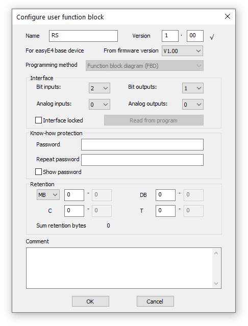 Figure 2. Window with function block properties
Our user function block will consist of only a few components: two gates, contacts at the input and coils at the output. You will also need to use a marker to couple the input to the output. For such a small number of components, a single network will suffice.
It would be more convenient to route the connections as shown in the diagram, but this is not possible. The components are placed by the software one after another, so we have to plan their “flat” arrangement. It is best to start arranging the user blocks from the NAND output element. Connect the output of the second NAND element and a contact to one of the inputs of the NAND output element. Then, connect two contacts to the input of the first NAND. What is left are the outputs – connect two coils to the second NAND gate. Now let's take a look at the properties of the individual contacts and coils:
- Contacts at the input (first NAND from the left):
- Type: Bit inputs/outputs and markers; Comment: SET; Bit logic: Break; Operand: I
- Input; Number: 1.
- Type: Bit inputs/outputs and markers; Bit logic: Make; Operand: M – Marker; Number: 1.
- Contacts at the output (second NAND):
- Type: Bit inputs/outputs and markers; Comment: Q; Coil function: Negated Contactor; Operand: Q
- Output; Number: 1.
- Type: Bit outputs and markers; Coil function: Contactor; Operand: M – Marker; Number: 1.
Now it's time to set the properties of the contact that feeds the RESET signal: Type: Bit inputs/outputs and markers; Comment: RESET; Bit logic: Break; Operand: I – Input; Number: 2.
The function block you've just made should look like the one shown in Figure 3.
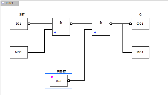 Figure 3. RS flip-flop function block
Click on the tab with the name of the block you've created and select Close. The software will ask you to save the block on disk – confirm and name the block. From now on, the definition is available from the list of blocks and ready to use.
Defining user function blocks is a great tool. With its help, you can create a library of ready-made solutions, which will considerably simplify the development of subsequent programs, and may also facilitate the work of your team or co-workers. You can also divide the work within your team – let everyone create and test a selected element, which will then be combined into a coherent whole. In the case of a simple program and the easyE4 controller by Eaton, this is not necessary, but it is a good work habit that can prove very beneficial when dealing with more complex projects.
Motion direction detector
In order to understand the operation principle of the motion direction detector, we recommend opening the software that is available in the supplementary content to the article. It is possible to place drawings of all described networks, but it is more convenient to view them (and the links between them) on the screen of the easySoft 7 programming environment. If in doubt, or if the description is too long, you can run the simulator and observe how the program behaves as you click through it – especially considering the fact that describing the functioning of networks (sometimes containing a single gateway) in isolation is not easy.
The diagram of the motion direction detector starts from network number 0010. From network number 0010 to 0016, there are logic elements corresponding to the operation of input I01, while from 0017 to the end, up to network number 0023, there are elements which support input I02. Both parts are symmetrical and they are modelled based on a pulse sequence detector (quadrature detector) with a D-type flip-flop. Since quadrature detectors work with signals that are shifted in phase by 90 degrees, and the one in the people counter must respond to sequences “none – I01 – none – I02 – none” or “none – I02 – none – I01 – none”, RS flip-flops have been added to memorise input states, to protect against voltage flickering at the inputs, and to achieve the phase shift which is necessary in a quadrature detector.
Timers have been added to both latches to time out the operation and generate a reset pulse for the input and output RS flip-flops, as well as gates to block the input pulses until the flip-flops are reset, i.e. ready for the next detection cycle. The individual components are arranged and connected in the diagrams in the same way as discussed earlier, and there is no point in describing it once again. Analysis of detector operation is best done using a simulator launched with the Simulation button. Unfortunately, the diagram in easySoft 7 has to be split into small networks, and is therefore difficult to analyse. For this reason, those who are inquisitive and willing to explore this subject in greater depth are recommended to print out the individual networks and draw a diagram that is made up of logic gates. It will then be easy to distinguish the D-type flip-flops and separate them from the added functionalities of blocking and resetting the flip-flops.
Saving the counter values in the event of a power outage
From the user's point of view, it would be convenient not to have to re-enter the settings in the case of a power failure, but only to adjust the value of the current indication if necessary. For this purpose, our program has to be able to store and retrieve the content of two counters – the C01 and C02 blocks.
The provider of the development environment calls the property of saving and restoring the state of blocks or markers retention. To read more about it, use the “Help” menu available by clicking on the “?” symbol located on the menu bar (you can also press F1). In the “Search” tab, type the word “retention”. You can also use the user manual available in the same menu.
For retention bytes, i.e. bytes that are retrieved after power-on, there is a memory of 400 bytes. Most probably it is a separate chip or a part of the CPU memory, powered by a separate source, e.g. a super capacitor or a battery. As stated in the help menu, storing/restoring the state of the “C” counter block requires 4 bytes of memory, so two counters can be easily accommodated in 400 bytes.
To enable saving/restoring the counter content, click on the “Project” button located in the lower left corner. Then, select the “System settings” tab. The third field from the left is “Retention” (Figure 4). At this point, it is worth paying attention to the value in the “Free:” field – in our example, the value shown is 400 bytes. Each “C” counter block requires 4 bytes.
 Figure 4. "Retention" field
For our program, the values of counter blocks C01 and C02 are important. Enter “01” in the box next to “C” and “02” in the next box , as in Figure 5. You can omit the other boxes, such as high-speed counter “CH”, incremental counter “CI”, data function block “DB” and timing relay “T”. Also, at this point, you don't have to worry about the markers (MW, MB, MD). It is easy to see that when the range is entered correctly, the value of “Free:” decreases by 8 bytes, which is the amount required to store values of the two counter blocks.
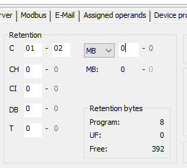 Figure 5. “Retention” field after entering the settings for C01 and C02 counters
Simulation of counter operation with easySoft 7
The easySoft 7 development environment has a built-in simulator that allows you to check the functioning of the program, see the state of inputs, outputs and logic levels of individual components of the FBD diagram. Using the simulator gives us the opportunity to test the operation of the program and to find bugs, although, for obvious reason, the simulator will not create the actual operating conditions that our application will encounter in reality. Now, let us use the simulator to check the operation of our people counter.
The simulator is started by clicking on the “Simulation” button located on the left, at the bottom of the easySoft 7 window. While simulating the work of the counter, let us leave most of the parameters as they are, we won't set any traps either, nevertheless the simulator features very interesting possibilities, which cannot be found in comparable competing products. Apart from setting traps, it allows, for example, to use a virtual oscilloscope, which presents the waveforms of selected signals. Let's try out its possibilities while testing our program.
With the program “People counter v11.e70” open, click on the ”Simulation” button, then expand the Display list above it and click on the Operand window + oscilloscope. An empty Operand window + oscilloscope will be shown on the right. Click on the asterisk symbol (*) in the Operand column and type M05. Next to it, in the Comment column, the message PULSE UP should appear. Click on the Oscilloscope column, a checkmark should appear together with a sort of logic state analyser channel in the Oscilloscope window. In the same way, add: M04 (PULSE UP), I01 (INPUT 1) and I02 (INPUT 2). The result should be as shown in Figure 4.
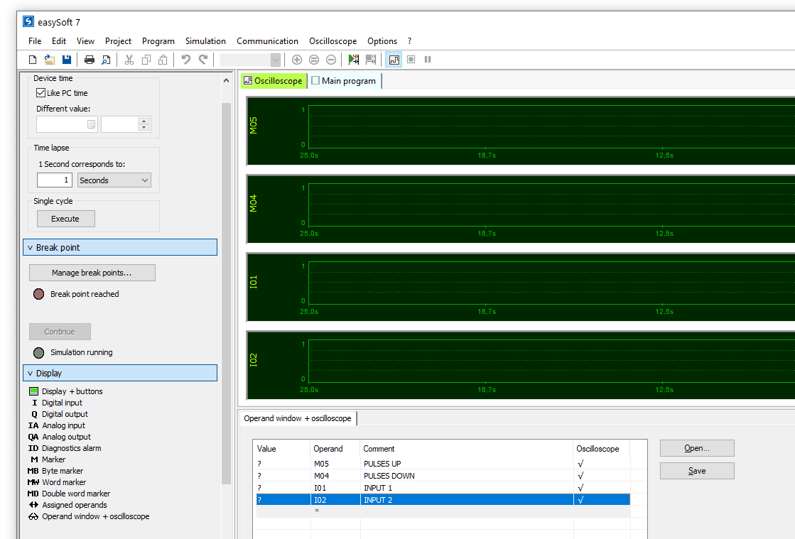 Figure 6. Configured oscilloscope window
Start the simulator by pressing F9 or selecting Simulation –> Start from the menu. From the menu, select Oscilloscope –> Recording on (or use the appropriate icon on the toolbar – a square with a red circle). On the left side of the screen, you should see the expanded Display list. Click on the Display + buttons. At the bottom of the window, the operating display of our counter will be shown. Here, use the right/left buttons to set the PERMITTED to a value greater than 0, for example 5, as in Figure 5. Now, click on Display –> Digital input, and then successively, double-click on the square next to 1:INPUT 1 and 2:INPUT 2.
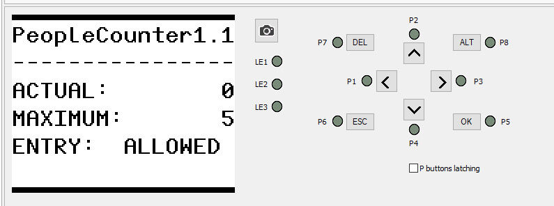 Figure 7. Counter display during simulation (with the maximum number of persons permitted in the room entered).
The effect of the oscilloscope' s operation is shown in Figure 6. You can see that the first pulse occurs at the input I01 and the next one at I02. Simultaneously with the rising edge at I02, a pulse is generated at the output M05:PULSE UP, causing the CURRENT value of the counter to increase by one, and showing this value on the display. Feeding the pulses in the reverse order generates a pulse at the output M04:PULSE DOWN and decreases the CURRENT value. It is still possible to add e.g. outputs to the oscilloscope screen and observe how the I/O levels change in relation to the pulses at I01 and I02, but in this situation this seems to be redundant information. The status of the outputs can just as well be observed by clicking on Display –> Digital outputs.
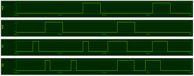 Figure 8. Waveforms at counter inputs/outputs during simulation
Thanks to the oscilloscope, it can be easily seen that the next person will be detected only after a pre-set timeout (here, it is 2.5 seconds), so if the barriers are placed close to each other, you can decrease this time. The oscillogram also shows that within a sequence of pulses at which the counter works correctly, these pulses may overlap, too. This is in case the barriers are mounted too close to each other. Once you have verified that the program is working, all you need to do is upload it to the easyE4 controller, feed the signals from the sensor inputs and connect the signalling device. Figure 7 shows a finished application enclosed in a plastic box, typically used for residential switchboards. Next to the controller, under a hinged cover, there is a reset button.
 Figure 9. People counter based on the easyE4 programmable relay
easyE4 controller – summary
In a series of three articles, we have discussed the design of a people counter. It can be used in two ways: either to signal that the permitted number of people in a room, as per the limit introduced in connection with safety requirements, has been exceeded, or to switch on/off lighting or ventilation in a room where these systems should operate only when someone is inside. The device uses the retention property, so the software works in such a way that the counter blocks containing the settings and the current status are stored in non-volatile memory and restored when the supply voltage is switched on. In the event of a power failure, it is therefore not necessary to set the counter parameters again – if needed, it is enough to count the persons present in the room and adjust the value.
Nevertheless, the easyE4 controller is a huge step forward compared to older products. The easySoft 7 development environment, which is already very good, will certainly undergo further improvements.
It used to be the case that application-specific controllers were most common. Now, as demonstrated by the example of easyE4, it is easy to see that it is not worth developing them based on available microcontrollers. For a relatively low price, you can get a controller with a fast processor, in a robust rail-mounted enclosure with a built-in display and keypad. It can be easily networked and communicated with, its functions can be upgraded and – which is extremely important in any professional application – it is compliant with numerous harmonised standards, including those for industrial environments. Therefore, you can be sure that you are getting a device whose core has been tested in a certified laboratory and which is backed by the brand and reputation of the manufacturer.
Transfer Multisort Elektronik (TME) is one of the world’s largest global distributors of electronic components, electrotechnical parts, workshop equipment, and industrial automation. The catalog includes over 1,500,000 products from 1,300 leading manufacturers. TME’s modern logistics centers in Łódź and Rzgów (Poland), with a combined area of over 40,000 m², ship nearly 6,000 packages daily to customers in more than 150 countries.
TME also invests in the development of knowledge and skills of young engineers and electronics enthusiasts through the TME Education project, and supports the tech community by organizing the TechMasterEvent series, promoting innovation and experience exchange.