Standards of electrical quantities
Standards of electrical quantitiesDate of publication: 29-10-2025 Update date: 30-12-2025 🕒 11 min read

Measurements must be based on some kind of standards. The vast majority of electronics engineers have not and will not have to deal with laboratory standards of electrical quantities. The best standards are unbelievably accurate, and although we don't deal with them, they are really worth knowing about.
- Which is more important: the ampere or the volt?
- Electrical voltage standards
- Resistance standards
- Current intensity standards
- Electrical charge standards
Piotr Górecki - popularizer of electronics. Currently publishes his own magazine "Understanding Electronics". Previously, for many years he was the Editor-in-Chief of a popular Polish magazine (Elektronika dla Wszystkich). He is also the author of hundreds of articles and educational projects. Until 1993, he worked in the telecommunications industry.
As electronic engineers, we make various measurements with different meters, most often multimeters. But also with the help of other, more and less complicated instruments.
But how do we know, that their indications are correct? It is not enough to trust the seller, that his meter "has the correct readings". The specification of the of the meter (multimeter), which, in the case of the cheapest instruments, is sometimes even "sucked from the finger", and in better cases incomplete, incomplete, inaccurate, and thus misleading.
So how can you check, whether the readings of your meter are correct?
Well, the simplest way is by comparing it with a better meter, at least a class better, whatever that would really mean. But this "better meter" also needs to be checked, probably with an "even better meter". And so on... And finally we come to the metrology laboratories, where there are not so much "best meters", but standards. Standards of electrical quantities.
In the past, the standard of the meter was a metal ruler locked in a safe in the palaces of Sevres near Paris, where the International Bureau of Weights and Measures is located, BIPM (fr. Bureau international des poids et mesures).
Today, neither the meter, nor other units have such material benchmarks. Especially after the reform of the year 2018, when certain physical constants were strictly defined, basic units were based on them and determined, how in laboratories these units can be reproduced, realized. What is important, in every country there is a state institution, which takes care of the compliance of national benchmarks with world benchmarks.
In any case, today you can "reproduce" the standards of units in any well-equipped laboratory. Also the standards of "electrical" units. And here begins an interesting, a little strange story.
Which is more important: the ampere or the volt?
In school we learn, that sI system of units of measurement is based on the following seven units: meter, kilogram, second, ampere, kelvin, candela and mol. Among other things, this is shown in the title figure of this article, which also indicates the relationship between units in the SI system before and after the reform of the year 2018. In the simplest terms, the reform based the basic units on certain physical constants. And the seven basic units are based on derived units, among others, the most interesting to us "electric", such as watts, joule, henr, farad, coulomb, hertz, om, simens i volt.
Of course, of these seven basic units, electronic engineers are most interested in the ampere. Recall, that at present this basic SI unit (of intensity) of electric current, is defined by taking a fixed numerical value of the elementary charge e, which is 1,602 176 634×10-19, expressed in the unit C (coulomb), which is equal to A ꞏ s, where a second is defined by ∆νCs. In view of this, is the basis and foundation of all electrical and electronic measurements the ampere? In laboratories, is this foundation the counting of the multitude (6,241509074 × 10¹⁸) of electrons flowing in one second?
Well, no! It may come as a surprise to many to learn, that electrical measurements are based on voltage standards and resistance standards, and not on standards of current or charge.
I emphasize, that the ampere is the basic unit of the SI system, but in practice the "ampere standard" is not used, only voltage and resistance standards, both based on quantum effects.
Electrical voltage standards
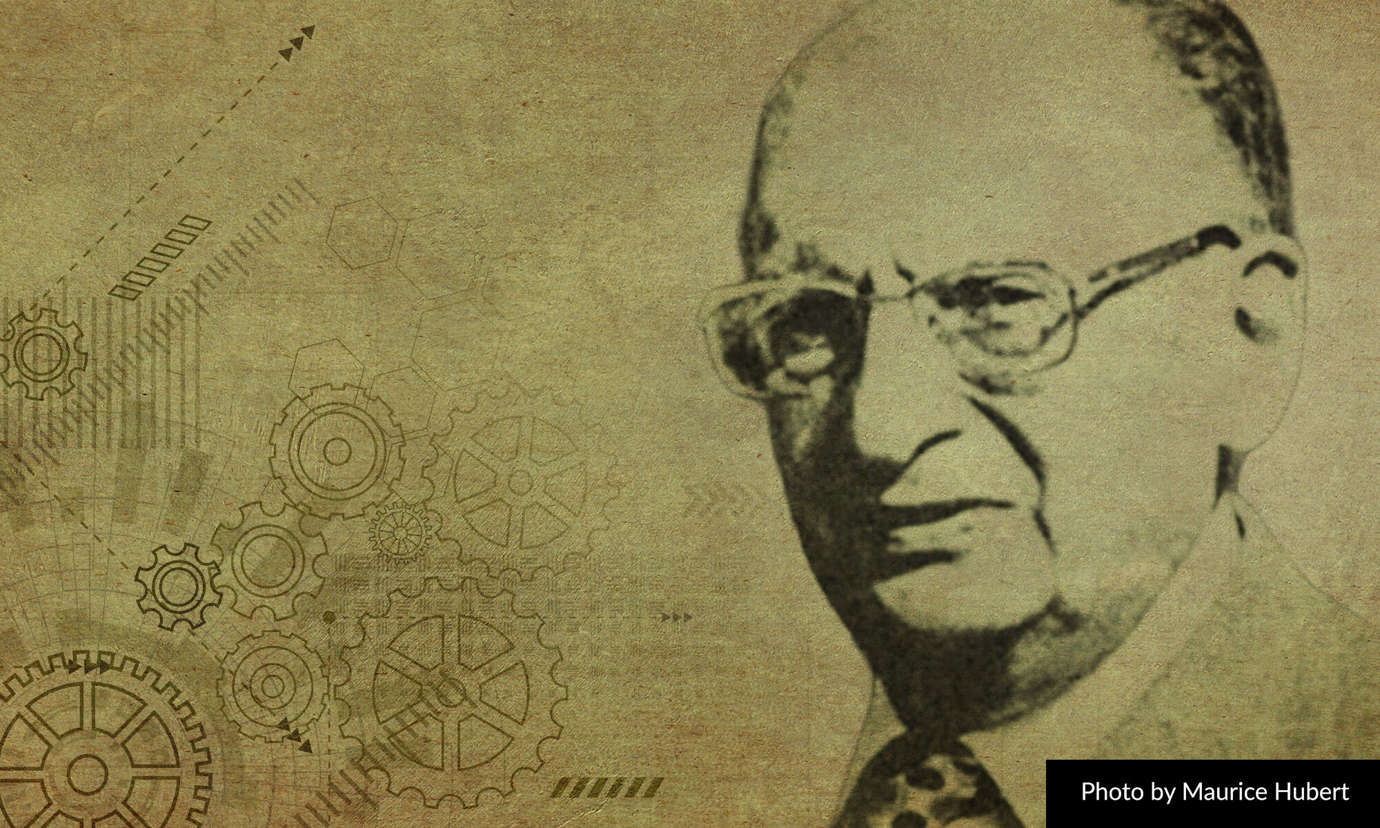
Electrical phenomena began to be studied intensively from the year 1800, mainly through the use of the volta stack. Others voltage sources were developed, mainly with low stability, which, by the way, was the cause of trouble, confusions and wrong conclusions. That is why in the years 20. XIX century Ohm, after initial misinterpretations, he used as a voltage source... thermocouples, rather than the Volta cell invented a quarter of a century earlier, having a very high internal resistance. Only then did he discover ohm's law.
 Figure 1
 Photograph 2
By contrast, in 1872 (others say 1873 or 1874), English engineer Josiah Latimer Clark developed a relatively stable cell, which more or less served as the official voltage standard until the end of the 19th century. Clark's cell was quite quickly replaced by one invented in the year 1893, much better, much more stable and more convenient to use the (Edward) Weston cell. The voltage of the Weston cell is about 1,01865V. About, because it also depends to a certain small extent on temperature. Figure 1 is from the original patent. Photo 2 (from Wikipedia, By Инженер Павел Серков CC-BY-SA 4.0) shows a practical implementation from the Soviet era.
Weston cells were the official voltage standards for almost a century, until 1990. They were superseded by incomparably better voltage standards using so-called Josephson Connectors.
Connectors, invented and described in 1962 by 22-year-old Brian David Josephson, the Josephson connector is a structure that uses a voltage pattern that can be used to connect the connector to the power supply-year-old Brian David Josephson at the time is a structure, in which two areas of superconductor are separated by a thin layer of insulator. Such a strange creation has numerous astonishing properties. Among other things, Josephson's connector is a... a frequency/constant voltage converter. "Illuminated" by microwave radiation, it produces a DC voltage directly proportional to the frequency of that microwave radiation.
There is no problem with producing microwave radiation at a very precisely defined frequency. Some problem is, that a single Josephson connector produces a voltage of less than 1 millivolt. Therefore, practically useful patterns with an output voltage of 10V contain cleverly implemented sets of thousands of elementary connectors connected in series, simultaneously excited by microwave radiation.
One Josephson connector gives a very small voltage, and in practice many such connectors connected in series are needed. On the one hand, this is an inconvenience, but on the other hand it allows to realize even more interesting programmable patterns, where the output voltage can be changed (PJVS - Programmable Josephson Voltage Standard, JAWS - Josephson Arbitrary Waveform Synthesizer). Such programmable sources allow to set with great precision not only the needed value of DC voltage, but also (somewhat similar to today's popular DDS generators) can be used to produce alternating voltage, including sinusoidal, and in quite a wide range of frequencies.
The main limitation is, that these are to be superconducting connectors, which in practice means the need to work at a temperature of several kelvins, which is close to absolute zero.Without going into details, it can be said, that the voltage standards using Josephson connectors provide accuracy better than 10-9, in other words, better than 0,001ppm, better than 1ppb - parts per billion, i.e 0,0000001%. This means, that in a good quantum 10-volt error is less than 0,01 microvolts, that is, from 10 nanovolts!
The need to work at a very low temperature in this respect is very beneficial, because it drastically reduces thermal noise - so you can realistically talk about nanovolts.
Quantum, superconducting standards are used to calibrate other, cheaper standards. But not Weston cells or related, only standards with semiconductor elements. The topic of voltage standards with conductive elements can be developed in other articles, and now just for the sake of orientation we will state, that the otherwise sensational lTZ1000 integrated circuit (ADR1000), considered the best solid-state voltage standard - if only because of noise and aging, has an accuracy roughly 1,000 times worse than Josephson's superconducting standards.
A hobbyist cannot dream of buying either a quantum calibrator, nor a top-quality professional solid-state one. However, today, also for amateurs, incomparably cheaper solutions of solid-state standards are available. They provide surprisingly high accuracy. Accuracy many times exceeding the capabilities of multimeters available to hobbyists. Without going into details: the error, or rather, the uncertainty of the best LTZ1000-based voltage standards realized by advanced amateurs can be of the order of 1ppm, i.e 0,0001%, at least in the short term. However, this is difficult to achieve for several reasons. But possible.
Integrated circuits LTZ1000 costs 330...400 pLN, the rest of the high-end components cooperating with it up to 1000 zł, which is quite expensive, but within the reach of quite a few hobbyists. On the other hand, it is relatively easy and cheap to make or buy for a few tens of zlotys a less accurate DC voltage standard, for example, with a simpler to use integrated LM399, 10...20 times inferior to the LTZ1000, but completely sufficient for checking even multimeters 5,5-digital. The main problem is the initial calibration of such a mid-range standard - it is so precise and stable, that for its calibration - to check its voltage, you need a really very accurate laboratory voltmeter or other good voltage standard. We will return to these threads, and for now let's discuss...
Resistance standards
Formerly the only, still in use today, most accurate resistance standards were very precise resistors, or rather sets of specially selected resistors.
Not coincidentally, these resistors are surprisingly large in size, often immersed in oil. And this is how even the most precise patterns used to be realized. This changed not so long ago, when born in the year 1943, in Sroda Wielkopolska, Klaus von Klitzing discovered the quantum Hall effect. "Ordinary" Hall effect is commonly used in magnetic field sensors, called hallotrons. The quantum Hall effect, on the other hand, is something significantly different. In the classical Hall effect, there is a voltage in the transverse axis of the sensor that is directly proportional to the direction and magnitude of the induction B. In the quantum Hall effect, it is not about the "transverse" voltage, but about the transverse resistance of the sample, as shown in Fig 4.
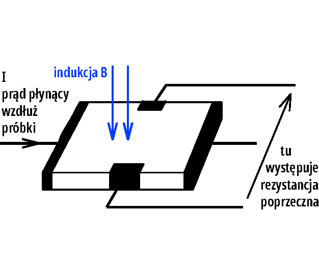 Figure_4
First, this can only occur in very thin active layers, which behave like a two-dimensional electron gas (2DEG). This, by the way, is closely related to MOSFET transistors, where current flows only in a thin layer of Semiconductors.
Secondly, occurs only in the presence of strong magnetic fields of the order of several tesla, that is, several times stronger than those produced by the strongest neodymium magnets. Thirdly, only at very low temperatures, close to absolute zero, usually around 4 kelvin, which is almost -270 degrees Celsius. And then, with the right choice of parameters, the (total) quantum Hall phenomenon.
 Figure 5
 Photograph_6
Roughly speaking, the idea is, that the (transverse) resistance of the Hall element can take on well-defined values. This is illustrated in Figure 5 (according to Wikipedia, Anticon CC-BY-SA 3.0). A realization of this type of element based on gallium arsenide (GaAs) is shown in photo 6 (from the German institute PTB, CC\N-BY-SA 4.0).
The basis is the so-called Klitzing constant, derived from two other fundamental physical constants
Without going into details, klitzing's constant is used today to define oma.
Thus, in this rather peculiar way, quantum resistance standards (QHR - Quantum Hall Resistance standard) were created with an accuracy better than 10-9, in other words, better than 0,001ppm, 1ppb, i.e 0,0000001%. For example,, if the standard had a resistance equal to 10kΩ (some have a resistance equal to half the Klitzing constant), then the error would not exceed 10mikroom, i.e 0,00001Ω.
These are, of course, very expensive laboratory standards, for the operation of which you need the temperature of liquid helium and a strong magnetic field. An example in the photo 7. These super-accurate quantum standards are used to calibrate classical standards, still having the form of a set of selectable resistors, enclosed in a rather large enclosure, often filled with oil.

Photograph_7
The quantum resistance standard has some improbably stable, but "non-circular" value of resistance, of the order of a few, dozen or more than twenty kilooms, and the classical resistance standards compared to it have different, mostly "round" values often in the range wider than 1Ω to 1MΩ.
It is necessary somehow to compare them with the quantum standard, which is not so easy, if the best possible accuracy is required. Here even the most accurate ohmmeter. For the calibration of resistance can be used classical measuring bridges, comparing voltage drops on the tested resistances, but also types of less known bridges, comparing not voltages, but currents.
We are now mainly talking about measuring and comparing resistances using direct current, but surprisingly and very interestingly, also uses for this... transformers. It may come as a surprise to many people to learn, that in general resistors, including voltage dividers, are a weak point, weak link in measurements and in Others precision circuits. Therefore, other ways of voltage division are used, among others using inductive voltage dividers. Inductive voltage dividers are one thing, and the other is current comparators, used to compare current and resistance.
The basic idea of using a transformer for comparison is child's play and is used in constant-current, hallotron, quite popular transformers. The current, flowing through the winding, produces a magnetic flux, proportional to the number of windings. If in the second winding the current flows in the opposite direction, it produces an oppositely directed magnetic flux). The measurement in total is to make the, that the two fluxes cancel each other out, exactly to zero. This depends not only on the magnitude of the currents, but also on the ratio of the number of coils. By changing in a clever way the number of active windings of one of the windings, we change the scale of comparison, so to speak, and can compare different currents and different resistances, according to the ratio of the number of windings of both windings. What is important, the number of windings is an extremely stable parameter, and this can provide great accuracy and stability. However, it should be emphasized, that the practical use of the potential possibilities is very difficult. Especially, when it comes to measurements at direct current. Already "ordinary" current comparators, called DCC or DCCT, allow comparisons with an accuracy (uncertainty) of the order of 10-6 , i.e. 1ppm. On the other hand, much higher accuracy of comparison is provided by so-called cryogenic current comparators (CCC - Cryogenic Current Comparator), where super-sensitive superconducting magnetic field sensors called SQUIDs are present, providing accuracy, or rather, an uncertainty even better than 10-9 (0,001ppm = 1ppb = 0,0000001%).
Earlier I mentioned, that today even hobbyists can and do realize, at a reasonable cost, voltage standards (of about 7V) with stability on the order of 1ppm ie 0,0001%. But for several reasons, the limitation turns out to be resistors. We will explore this topic in separate articles.
For now, we will only add, that for comparing, and, in general, also for measuring resistance, so-called Hamon transfers are used. Hamon transfer and Hamon divider are old, dating from the years 50. 20th century, surprisingly simple, but also surprisingly accurate methods used for precise measurement of resistances and voltages.
Current (amperage) standards
As already mentioned, the ampere is the basic unit of the SI system, but in laboratory, and even more so in workshop practice, special super-precision current (amperage) standards are not used. Current is measured as a voltage drop across a resistance.
Thus, to accurately measure current, you need standard voltage sources and standard resistances. Others are used to calibrate and calibrate meters calibrators, including current calibrators (current sources), but their accuracy is determined by the parameters of the voltage standards and resistances used in them.
Electrical charge standards?
It is difficult to talk about charge standards. Electric charge can be accurately determined, precisely by measuring current and time, possibly capacitance and voltage
We are not talking about charge measurements in the case of charging and discharging Rechargeable Batteries, where high accuracy is not needed. In general, not only hobbyists really very rarely have to deal with accurate charge measurement. If at all, it is sometimes when measuring extremely small currents, less than 1 pico ampere.
Usually this is also related to capacitance, and it would be more appropriate to talk about capacitance patterns. To this interesting, little-known thread of charge measurements we can also return to. And in the next article of this series we will begin to discuss the basic limitations of accuracy and stability.
Piotr Górecki
Transfer Multisort Elektronik (TME) is one of the world’s largest global distributors of electronic components, electrotechnical parts, workshop equipment, and industrial automation. The catalog includes over 1,500,000 products from 1,300 leading manufacturers. TME’s modern logistics centers in Łódź and Rzgów (Poland), with a combined area of over 40,000 m², ship nearly 6,000 packages daily to customers in more than 150 countries.
TME also invests in the development of knowledge and skills of young engineers and electronics enthusiasts through the TME Education project, and supports the tech community by organizing the TechMasterEvent series, promoting innovation and experience exchange.