Unipolar transistors
(19 008)Unipolar transistors, like bipolar transistors, are electronic devices used to amplify electrical signals. High power signal can be controlled using a low power signal. Thus, the transistor can be used as a switch. Unipolar transistors are used in converters, power amplifiers, inverters, and related devices. It is worth mentioning here that processors, for example, are composed of billions of transistors.
Types of unipolar transistors
There are several types of unipolar transistors, among which are J-FETs (Junction Field Effect Transistor), MOSFETs (Metal Oxide Semiconductor FET) or TFTs (Thin Film Transistor). Several other types of unipolar transistors can be found, but in practice the first two types are most often used in electronic circuits. TFT transistors, on the other hand, are mainly used in liquid crystal displays (LCDs).
Construction and operation of unipolar transistors
Unipolar transistors have three terminals called drain, source, and gate. Considering that unipolar and bipolar transistors are most often found in the same packages and perform almost identical functions, it is difficult to distinguish them from each other at first glance. However, it should be remembered that both have a different structure.
J-FET field effect transistors are electric field controlled transistors. The construction of this type of transistor is based on the use of a layer of n-type or p-type semiconductor to which the drain and source terminals are connected, and a semiconductor with low doping opposite to that of the channel, which usually surrounds the transistor channel and to which the gate terminal is connected. The doping of the semiconductor forming the channel determines whether it is an n-type (N-JFET) or p-type (P-JFET), the latter being much less common.
As an example, let's describe the operation of an n-type J-FET unipolar transistor. If a voltage is applied between the drain and source, the current flows between the source and drain. In the case of a negatively polarised gate, i.e. when the voltage applied to the gate is negative with respect to, the source, the current that flows through the channel of the transistor will start to decrease and disappear. This is because the depletion region between the drain and the source will start to expand. If the value of the voltage difference between the gate and the source is high enough, i.e. for an n-type J-FET transistor, the voltage at the gate will be low enough, the current will stop. Usually, this voltage is a few volts and depends on the particular type of transistor. In this state, the transistor is said to be in the cut-off, the resistance between source and drain is extremely high (measured in giga-ohms [GΩ]). It is worth noting that the unipolar transistor acts as a voltage-controlled device. Virtually zero current flows between the gate and the source.
Unipolar MOSFET transistors
Another type of commonly used unipolar transistors is the MOSFET transistor. In this case, the metal gate is insulated from the channel by a layer of silicon dioxide. The main and largest part of the MOSFET is the lightly doped p-type or n-type semiconductor connected with the base region and two highly doped regions of opposite polarity. They are connected to source and drain terminals. They determine whether the transistor is of the P-type or N-type. When there is no voltage difference between the individual terminals of a unipolar transistor, the two P-N junctions between the source and drain form two diodes connected in series. In such a case, one of them is negatively polarised, so there is no possibility for current to flow through such a transistor (unless the applied voltage exceeds the maximum permissible value). However, if a sufficiently high voltage of appropriate polarity is applied at the gate, which is located between the source and drain (e.g. in the case of an n-type transistor this will be a positive voltage with respect to the source) and the threshold voltage is exceeded, the interaction of the electric field with the layer of lowly doped semiconductor underneath will result in the formation of the so-called inversion layer. This creates a channel that connects the source and drain terminals. The current that can flow through the transistor depends on the voltage applied to the gate terminal and is a linear relationship, but only up to a certain value of the drain current. Of course, there is also a voltage value applied to the gate terminal above which the current remains constant and no longer increases; this is called the saturation voltage.
The case described earlier concerned a MOSFET with an n-channel in the enrichment regime. Such a transistor is normally closed and opens upon application of a gate voltage, while there are also depleted channel transistors which are far less common and in which, if the gate has the same potential as the source, it is open and conducts current.
The MOSFET transistor acts a bit like a capacitor and exhibits a relatively large capacitance. For this reason, changing the state of such a transistor at high frequency can be problematic, as it takes some time to charge and discharge the capacitance at the gate, and thus to change the conduction state of the device. For this reason, the MOSFET control systems must be characterized by high current efficiency. MOSFETs have a diode between the drain and the source (sometimes referred to as a parasitic diode). As mentioned above, the internal diode is a consequence of the MOSFET structure. This is important information in the case of AC control.
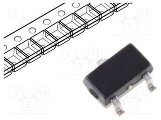
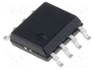
Unipolar transistors are available in both through-hole and surface-mount packages. For this reason, they are available in a wide variety of packages, among which the most popular are DPAK, D2PAK, TO220, TO247, or SOT23. They usually have three leads (not including multichannel transistors).
Parameters and characteristics of unipolar transistors
Parameters that are important when selecting a suitable transistor include the maximum drain-source voltage (specified in volts[V]), the maximum gate-source voltage, which in this case is the control voltage, the maximum drain current (in amperes [A]), power dissipation (in watts [W]), and the conduction resistance in ohms[Ω] or milliohms [mΩ]). Exceeding the maximum voltage or current may lead to malfunction or irreversible damage to the device. In addition, the excessive current may cause overheating and damage of the unipolar transistor. In practice, additional heat sinks are used which are in contact with the device and thus enable more efficient heat dissipation to the environment. In some cases (e.g. in switching power supplies), forced air circulation by fans is used to improve cooling.
Warehouse: