PLC controller programming languages
PLC controller programming languagesDate of publication: 03/14/2025 🕒 6 min read
PLC controllers are commonly used in industry wherever parameter control and process management are necessary. The development of embedded electronics has resulted in devices with high specifications, resistant to EMI disturbances and environmental conditions, while being user-friendly. Unlike in the past, environments for creating programs are very similar to each other, and most of them offer a way to execute a program that suits us. So how do you program a PLC controller?
Programming languages for PLC controllers became the subject of IEC 61131 standard published in 2013. Part 3 of this standard contains recommendations regarding languages and methods for programming PLC controllers. In addition to data types, variables, configuration and its description, program organization units, and object-oriented programming principles, five basic programming languages for PLC controllers are listed, and requirements for their functionality are defined. Due to this standard, the basic programming languages used by PLC programmers have become:
- Ladder Diagram (LD or LAD; Ladder, LADder – ladder),
- Functional Block Diagram (FBD),
- Structured Text (ST, STX),
- Sequential Function Chart (SFC),
- Instruction List (IL).
Ladder LD (LAD)
The most popular and available in all environments for creating programs for PLCs is the Ladder Diagram LD (or LAD). It is a graphical language, but it uses uncomplicated symbols, so in older solutions, semigraphics created using standard ASCII characters were used. These characters were easy to present on the PLC screen as well, allowing for simpler ad hoc programs without using a PC. In this language, a program diagram is created using symbols similar to those used in electrical diagrams – coils and contacts. Contacts can be normally open (NO) or normally closed (NC), and coils can have various functionalities, such as setting, resetting, or negating. Functions and entire functional blocks, such as timers, counters, or flip-flops, can also be interwoven here. The ladder language is understandable even for an inexperienced programmer.
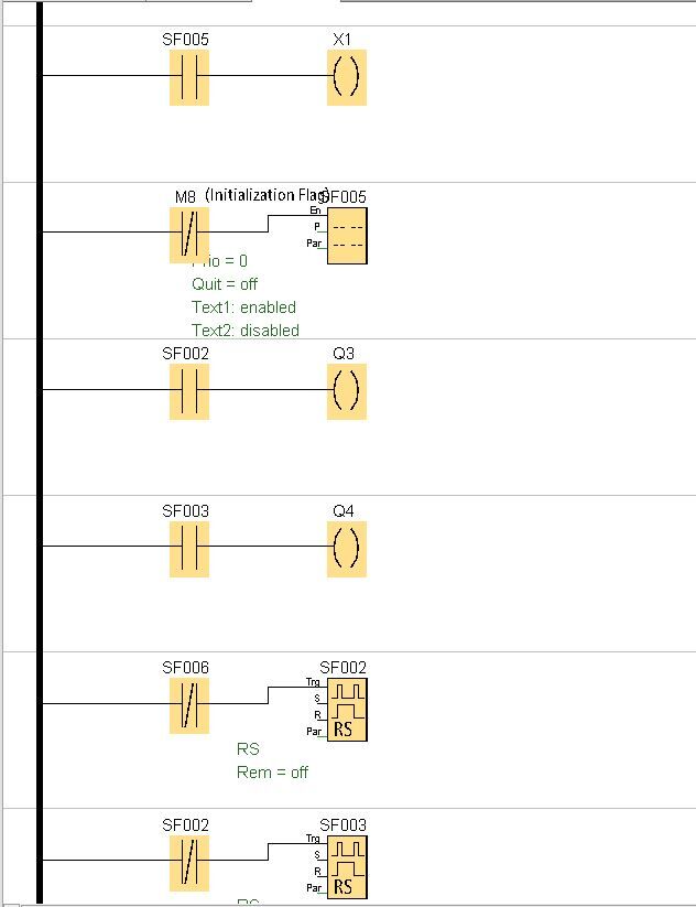
Figure 2. Example fragment of a program executed using FBD
Functional Block Diagram FBD
Another very intuitive way of programming, especially for those familiar with digital technology, is the Functional Block Diagram FBD. An example fragment of "code" executed using FBD is shown in Figure 2. Individual inputs, outputs, and operations are represented by functional blocks and gates that perform not only logical functions but are also capable of processing signals according to a given algorithm. Among the functional blocks are PID controllers, a wide range of waveform generators, counters, and others. Some programming environments also allow for defining custom blocks with required functionality. FBD is a graphical language. Individual blocks are arranged on a diagram and connected, resembling the drawing of logic circuits. Some programming environments allow not only for connecting inputs/outputs but also for creating buses and references that transmit a series of parameters (in Figure 2, buses are represented by bold lines – here they transmit multi-bit constants and variables).
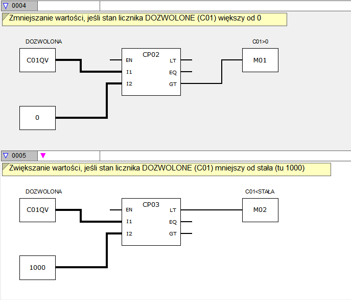
Figure 2. Example fragment of a program executed using FBD
Structured Text ST
Structured Text ST is a high-level language reminiscent of the once very popular Pascal language. It allows for more complex operations, whose notation is not limited by a tangle of lines on the screen and their execution capability as in the case of FBD, which often requires a large monitor with good resolution. Programming in ST resembles writing code in traditional programming languages for PCs. Complex instructions are supported, such as repeat…until loops, do…while, conditional instructions if…then…else, case, and mathematical functions sqrt(), sin(). Importantly, regardless of the hardware manufacturer or environment, ST language functions are common to them and have been defined in the IEC 61131 standard. Since the mentioned standard allows for combining the languages listed in it, ST can also be used to create "inserts" or non-standard FBD blocks.
Listing 1. Example function executed in ST language
//=======================================================================
// Function Block Timed Counter :  Incremental count of the timed interval
//=======================================================================
FUNCTION_BLOCK FB_Timed_Counter
    VAR_INPUT
        //Trigger signal to begin Timed Counting
        Execute     : BOOL := FALSE;
        //Enter Cycle Time (Seconds) between counts
        Time_Increment  : REAL := 1.25;
        //Number of Desired Count Cycles
        Count_Cycles    : INT  := 20;
    END_VAR

VAR_OUTPUT
        //One Shot Bit indicating Timer Cycle Done
        Timer_Done_Bit  : BOOL := FALSE;
        //Output Bit indicating the Count is complete
        Count_Complete  : BOOL := FALSE;
        //Accumulating Value of Counter
        Current_Count   : INT  := 0;
END_VAR

VAR
        //Timer FB from Command Library
        CycleTimer      : TON;
        //Counter FB from Command Library
        CycleCounter    : CTU;
        //Converted Time_Increment in Seconds to MS
        TimerPreset : TIME;
    END_VAR

    // Start of Function Block programming
    TimerPreset := REAL_TO_TIME(in := Time_Increment) * 1000;

    CycleTimer(
        in := Execute AND NOT CycleTimer.Q,
        pt := TimerPreset);

        Timer_Done_Bit := CycleTimer.Q;

        CycleCounter(
        cu := CycleTimer.Q,
        r := NOT Execute,
        pv := Count_Cycles);

        Current_Count := CycleCounter.cv;
        Count_Complete := CycleCounter.q;
END_FUNCTION_BLOCK
Sequential Function Chart SFC
The Sequential Function Chart is another graphical programming language. Its prototype was the GRAFCET language modeled on binary Petri nets. It allows for describing sequences of steps (actions) that are to be executed in a strictly defined order. It is particularly useful for creating programs for handling processes requiring synchronization or processes that can be divided into stages. The main components of a program in SFC are: steps (stages) associated with actions, transitions associated with logical conditions, direct connections between steps and transitions.
Often, the SFC language is combined with another programming method, such as the LD ladder. SFC is inherently a concurrent programming language, where many POU (Program Organization Units), i.e., units controlling the flow, can be active simultaneously. Some environments also allow for creating macro actions, i.e., actions within a POU that affect the state of another POU. In this way, one POU can determine the active steps taken by another POU.
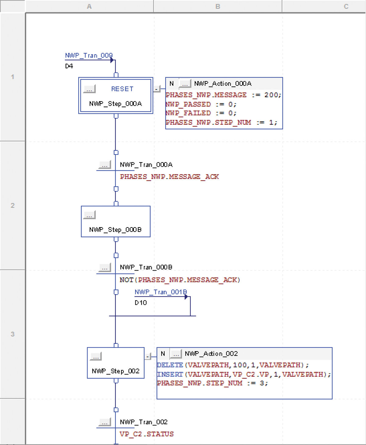
Figure 3. Example fragment of a program in SFC language
Instruction List IL
The instruction list is now considered an outdated way of programming. This language somewhat resembles assembler, but despite being implemented for different PLC controllers equipped with different processors, the IL language is independent of the type of processor used. Like assembler, it consists of very simple instructions, and more complex operations require the use of many of them. Program execution control is carried out using jump instructions and subroutine calls.
Many controller manufacturers, despite full compliance of the offered hardware and software with the IEC 61131-3 standard, offer additional calls/functional blocks specific to a given supplier and adapted to the hardware offered by them, such as reading or writing to inputs/outputs. For example, the IL language intended for Siemens PLC controllers was named "Statement List" or "STL" in English and "Anweisungs-Liste" or "AWL" in German. The German name was also transferred to the national versions of the runtime environment in Italian and Spanish. A Simatic package user can choose between German and international mnemonics to represent instructions. For example, "A" means "AND" or "U" means "UND", "I" means "Input" or "E" means "Eingang", etc.
Listing 2. Example fragment of a program in IL language
        LD      Speed
        GT      2000
        JMPCN       VOLTS_OK
        LD      Volts
VOLTS_OK    LD      1
        ST      %Q75
Which language is the best? It depends…
The purpose of this text is not to teach PLC controller programming but to signal certain possibilities and options to choose from. Every PLC programmer should choose a method that is most appropriate for their needs or combine them depending on the application. For example, the FBD diagram will likely appeal to users who know and understand logic circuits, while the LD ladder will be useful for programming simpler control sequences. On the other hand, ST and SFC will be suitable for programming complex processes, although, for example, the ST language has been implemented in Eaton's Easy micro PLC controller, which is more likely to be used for simpler, less demanding control and monitoring functions. On the other hand, there are no recommendations stating which language can be used for what, which is suitable for what. With more or less effort, using any of the discussed methods, appropriate software can be created. The best option seems to be combining languages depending on needs and to achieve the greatest readability of the application.
Transfer Multisort Elektronik (TME) is one of the world’s largest global distributors of electronic components, electrotechnical parts, workshop equipment, and industrial automation. The catalog includes over 1,500,000 products from 1,300 leading manufacturers. TME’s modern logistics centers in Łódź and Rzgów (Poland), with a combined area of over 40,000 m², ship nearly 6,000 packages daily to customers in more than 150 countries.
TME also invests in the development of knowledge and skills of young engineers and electronics enthusiasts through the TME Education project, and supports the tech community by organizing the TechMasterEvent series, promoting innovation and experience exchange.